the Creative Commons Attribution 4.0 License.
the Creative Commons Attribution 4.0 License.
Significance of substrate soil moisture content for rockfall hazard assessment
Valerie Zimmer
Christopher White
Chris Massey
Tim Davies
Rockfall modelling is an important tool for hazard analysis in steep terrain. Calibrating terrain parameters ensures that the model results more accurately represent the site-specific hazard. Parameterizing rockfall models is challenging because rockfall runout is highly sensitive to initial conditions, rock shape, size and material properties, terrain morphology, and terrain material properties. This contribution examines the mechanics of terrain impact scarring due to rockfall on the Port Hills of Christchurch, New Zealand. We use field-scale testing and laboratory direct shear testing to quantify how the changing moisture content of the loessial soils can influence its strength from soft to hard, and vice versa.
We calibrate the three-dimensional rockfall model RAMMS by back-analysing several well-documented rockfall events that occurred at a site with dry loessial soil conditions. We then test the calibrated “dry” model at a site where the loessial soil conditions were assessed to be wet. The calibrated dry model over-predicts the runout distance when wet loessial soil conditions are assumed. We hypothesize that this is because both the shear strength and stiffness of wet loess are reduced relative to the dry loess, resulting in a higher damping effect on boulder dynamics. For both realistic and conservative rockfall modelling, the maximum credible hazard is usually assumed; for rockfall on loess slopes, the maximum credible hazard occurs during dry soil conditions.
- Article
(4711 KB) - Full-text XML
- BibTeX
- EndNote
The distribution of rockfall deposits is largely defined by topography, physical properties of the boulder (block shape, size, and geology), boulder dynamics (block velocity, rotations, bounce height, and impact and rebound angles), and substrate properties (Wyllie, 2014; Wyllie and Mah, 2004). Ground conditions will influence how much the kinetic energy of the block is reduced on impact with the substrate (Dorren, 2003; Evans and Hungr, 1993). A block impacting colluvial material or outcropping rock will retain much of its energy due to the stiffness of the surface. If the block impacts softer ground, some of the block's kinetic energy will be dissipated as the soil deforms (Bozzolo and Pamini, 1986). Terrain material parameters in soil slopes will change seasonally, having a variable effect on rockfall runout behaviour; this is especially important for cohesive soils, where the changes in soil deformation behaviour in the plastic and liquid states are significant.
In situ rockfall experiments and other field data show that ground conditions have an influence on rockfall dynamics (Peng, 2000; Azzoni and de Freitas, 1995; Chau et al., 1998; Giani et al., 2004; Dorren et al., 2005; Ferrari et al., 2013; Volkwein et al., 2018). The analysis of block impact characteristics (e.g. Leine et al., 2013) allows for development of more realistic numerical simulation models. Within these models, terrain types must be accurately delineated and characterized for results to be meaningful (Dorren, 2003). Terrain types need to be delineated according to the behaviour that most affects rockfall dynamics, by dividing substrate material into soft and hard portions. Hardness, the amount of plastic resistance to localized impact, will control how much energy is dissipated on boulder impact with the ground. We theorize that the hardness of soil is controlled by the shear strength and stiffness of the soil. These properties will have an effect on the dynamics of rockfall propagation. Where material shear strength and stiffness vary with soil moisture content, it is necessary to determine whether soils are dry or wet and to assign specific “terrain” parameters to model the frictional forces that will be applied to a boulder during impact as it travels across them. In this paper the term “dry” is used to indicate a soil with low natural moisture content, typically well below the plastic limit.
Discrete rockfall boulder runout events on the loessial soil slopes of the Port Hills, Christchurch, are affected by variations in soil moisture content (e.g. Carey et al., 2017), which can cause soil hardness to dramatically change their effect on rockfall runout. Constraining rockfall modelling parameters to better reflect actual rockfall behaviour requires characterization of soil hardness changes due to moisture content. In this paper, we analyse the results from two recorded rockfall events on loessial slopes in the Port Hills, Rapaki Bay and Mt Vernon. Both sites have similar substrate material, slope gradient, roughness, aspect, and density of vegetation. The three-dimensional rockfall model RAMMS was calibrated to a rockfall event (comprising the fall of multiple rocks) that occurred in dry conditions (Borella et al., 2016). The calibrated model was then tested by forecasting rockfall runout on a different slope when the loessial soil was wet. This was done to provide a data set and methodology for practitioners to apply when carrying out rockfall hazard and risk assessments under both wet and dry soil conditions.
The Port Hills form part of Banks Peninsula, a volcanic edifice situated to the south-east of the city of Christchurch (Fig. 1). It was volcanically active in the middle–late Miocene, 11–5.8 Ma (Hampton and Cole, 2009). Hawaiian-style eruptions resulted in conical basaltic lava flow deposits radiating outwards from three principal eruptive centres and associated local vent structures (Brown and Weeber, 1992; Hampton and Cole, 2009; Hampton et al., 2012). An extended period of volcanic quiescence allowed widespread deposits of aeolian silt, the Banks Peninsula loess, to accumulate on the volcanically formed slopes (Griffiths, 1973; Goldwater, 1990). These loessial soils are a product of proglacial fluvial action and wind transport/deposition (Davies, 2013); the dominantly quartz (> 50 %) and feldspar (> 20 %) composition of the soil reflects the schist–greywacke mineralogy of the Southern Alps (Griffiths, 1973; Claridge and Campbell, 1987; Bell and Trangmar, 1987). Post-depositional slope processes have resulted in reworking of the loess and loose volcanic material to form colluvium on the lower slopes, reaching 40 m thick in some foot-slope locations (Mcdowell, 1989; Jowett, 1995; Claridge and Campbell, 1987). Close to the underlying basaltic bedrock, mixed loess–volcanic colluvium is often recognized in the regolith profile (Bell and Crampton, 1986; Bell and Trangmar, 1987).
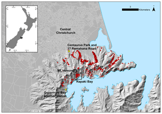
Figure 1Location map of Christchurch and the Port Hills showing sites examined in this study. Red dots show mapped rockfall deposit locations (n=5719).
2.1 Port Hills rockfall
The Canterbury Earthquake Sequence (CES) of 2010–2011 on the previously unmapped Greendale and Christchurch fault traces to the west and east of Christchurch produced seismic moments up to Mw 7.1 and high peak ground accelerations (≥1 g) (Holden, 2011; Cousins and McVerry, 2010; Bannister and Gledhill, 2012; Wood et al., 2010; Beavan et al., 2011; Fry et al., 2011a, b; Kaiser et al., 2012). These large, shallow (< 15 km) ruptures triggered large slope failures on the Port Hills, of which rockfalls were the most abundant type and posed the most risk (Massey et al., 2014b). More than 6000 individual boulders were mobilized, many of which impacted houses and affected the livelihoods of people within the impacted area. Rockfall is most likely to occur in closely jointed or weakly cemented material on slopes of ≥40∘ (Keefer, 1984). The columnar jointed lava of the Port Hills is generally dominated by three to four joint sets (Brideau et al., 2012) which vary somewhat between sites, attributed to variations in the paleotopography (Massey et al., 2014b). Scoria layers are interbedded with lava in some sites, and these have more widely spaced discontinuities than the lava (Massey et al., 2014b). Rockfall data were collected by a rapid-response group immediately following events of the CES and resulted in a repository of data including 5 719 boulder locations (Massey et al., 2014b), with their associated earthquake event and boulder dimensions (Fig. 1).
2.2 Geotechnical properties of loess
Loess is defined as a loosely deposited aeolian soil of predominantly silt-sized particles. Loess often displays high enough strength and cohesion to allow deposits to be meta-stable in a near-vertical exposure in dry conditions. When dry, the high cohesion of loess has been attributed to several possible mechanisms, including clay cohesion, calcite bonding, and soil suction (e.g. Goldwater, 1990). Post-depositional flocculation of cohesive clay grains to the larger silt- and sand-sized grains causes the irregular formation of clay “bridges” between larger grains. As the larger grains within the soil do not touch, the mechanical behaviour of the material is dominated by the bonds between the larger grains (Gao, 1988; Lutenegger and Hallberg, 1988; Derbyshire and Mellors, 1988). Due to the cohesion between clay particles and negative pore pressure above any water table, loess generally displays a high dry shear strength; up to 180 kPa has been reported in Christchurch in loess of < 10 % moisture content (Mcdowell, 1989). However, loess has been observed to lose significant strength and cohesion upon wetting, with cohesion and friction angle generally decreasing with increasing moisture content (Kie, 1988; Mcdowell, 1989; Della Pasqua et al., 2014; Carey et al., 2014). Wetting of the clay bridges and an increase in pore pressure reduces the shear strength of the material (Gao, 1988; Lutenegger and Hallberg, 1988; Derbyshire and Mellors, 1988; Della Pasqua et al., 2014; Carey et al., 2014).
The Port Hills loess is a cohesive predominantly silty soil with minor clay content. Strength parameters of the soil are largely controlled by the moisture content as repeatedly shown in testing (e.g. Tehrani, 1988; Mcdowell, 1989; Goldwater, 1990; White, 2016; Della Pasqua et al., 2014; Carey et al., 2014). A review of these studies (Massey et al., 2014a) shows that it displays high cohesion at moisture contents of < 10 %, while cohesion values are very sensitive to changes in the moisture content between 10 % and 20 % tests. Carey et al. (2014) found that at 3 % moisture content the loess has cohesion of 45 kPa and a friction angle of 48∘. Comparatively at 16 % moisture content the soil displayed cohesion of 25 kPa and a friction angle of 28∘. At moisture contents less than 15 % the soil can display a brittle deformation style. The measured plastic limit for the Port Hills loess is a moisture content ranging from 16 % to 20 %, with a plasticity index of between 4 and 8.8, and liquid limit ranging between 22 % and 28 %, above which the material deforms as a fluid (Hughes, 2002).
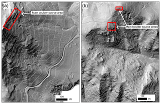
Two Port Hills rockfall events are compared (Fig. 2). The initial RAMMS model calibration at Rapaki Bay (Borella et al., 2016) back-analysed mapped rockfall deposits from the 22 February 2011 (NZST) earthquake. The calibrated model is then tested against data from a field experiment at Mt Vernon conducted on the 12 May 2014. Both slopes (which are within 0.6 km of each other; Fig. 1) have similar gradient (Fig. 2), aspect, and density of vegetation. Rapaki Bay is a south-east-facing, moderately inclined (average 25∘) slope with grass and tussock vegetation. The source area bedrock ranges from moderately to completely weathered basaltic lava and basaltic lava breccia, and the slope is mantled by loess and loess–colluvium. The slope is situated above a small community; more than 200 boulders were released here during the 22 February 2011 earthquake, impacting several houses. The slope falls from the peak (390 m a.s.l.) to sea level, with a runout zone ca. 900 m long.
Mt Vernon is a south-facing, moderately to steeply inclined (25–35∘) slope in the Port Hills. Geology at Mt Vernon is similar to Rapaki Bay; outcropping bedrock also ranges from moderately to completely weathered basaltic lava and basaltic lava breccia (again forming the rockfall sources). The slope is mantled by loess and loess–colluvium. The site was chosen due to its proximity to Rapaki Bay, its similarity in terms of materials, slope gradient, roughness, and aspect, and low vegetation density, and because it has a safe zone for physical runout experiments. There is an obvious discontinuous rockfall source area above a well-constrained long (∼700 m) runout zone, and the uninhabited valley extends over 1.5 km from the boulder source areas to the nearest road, downslope.
4.1 Mapping and soil moisture at Rapaki Bay
Boulder deposit locations were measured in the field using a handheld GPS. Boulder size (lengths along three axes) and shape were recorded for most mapped boulders. New rockfall deposits were easily distinguished from paleo-boulders by fresh rock surfaces and their location on top of the substrate. Impact scars on the substrate were mapped at both Rapaki Bay and Mt Vernon with lengths (axis parallel to boulder travel direction) and depths of 140 scars recorded. Additional mapped earthquake boulder data were contributed by the Port Hills Geotechnical Group – only boulder deposit locations were used from this data set. In total 336 boulders were mapped at Rapaki Bay.
To assess soil moisture conditions at the time of the earthquake, weather data were accessed through the National Climate Database (CliFlo; http://www.cliflo.niwa.co.nz, last access: 11 January 2019) from the Governors Bay station, 3.5 km south-west of the site and also south-east-facing (Fig. 1). The Governors Bay rainfall data are presented in Table 1. Moisture content of the soil at Rapaki Bay was not tested at the time of the earthquake and instead inferred from published testing of 14 Port Hills loess samples in January and February 2013 and 2014 (taken from the northern side of the Port Hills: Lucas Lane, Maffeys Road, Redcliffs, Deans Head, Clifton Hill, Richmond Hill, and Wakefield Avenue; Carey et al., 2014).
Table 1Rainfall data (mm) recorded at the Governors Bay weather station between 2010 and 2014, with the weather station average over 20 years provided for comparison. Bold indicates months of interest in this study.

1 Rainfall preceding earthquake rockfall event, Rapaki Bay. 2 Rainfall preceding and during Carey et al. (2014) testing, summer 2013. 3 Rainfall preceding and during Carey et al. (2014) testing, summer 2014. 4 Rainfall preceding field experiments, Mt Vernon.
4.2 Soil testing
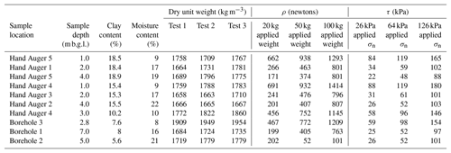
We conducted moisture content and direct shear tests on 36 disturbed hand auger and borehole samples of Port Hills loess and loess–colluvium from 17 Ramahana Road and Centaurus Park (Fig. 1). Unfortunately no sub-surface investigations could be undertaken at Rapaki Bay, and as such testing was carried out on samples taken on similar soil types from a site investigation that was underway at the time of the study (White, 2016). Samples were taken from a range of soil profile depths (Table 2) and as such reflect a range of clay and natural moisture content and therefore mechanical properties. Testing was in accordance with ISO/TS 17892-10:2004 Direct shear tests and NZS 4402:1996 Test 2.1 Determination of the water content. Samples selected displayed a spread of both clay contents (Table 2; 5 %–19 %) and natural moisture contents below, near, and above their 16 %–19 % plastic limit (Table 2; 8 %–22 %). The samples were reconsolidated by means of tamping, using a standard Proctor test within the shear-box test sample rings. A total of 25 blows from the hammer were used to compact the soil directly into the shear-box test sample ring, and the method was repeated with a fresh sample if the blows from the hammer caused the soil to be compacted to below or > 5 mm above the height of the sample ring. The method was considered satisfactory; however there was an unavoidable amount of variation in the density of the samples: the dry density varied between 1658 and 1954 kg m−3, with an average of 1750 kg m−3. This variation can be attributed to the variable moisture contents of the soils that were compacted, which would have allowed greater or lesser compaction depending on the optimum moisture content for compaction and the soil's particle-size distribution. The samples were subjected to 20, 50, and 100 kg applied weight (corresponding to 26, 64, and 126 kPa normal stress and overburden depths of 1.45, 3.64, and 7.28 m respectively with consideration of the average sample density (1750 kg m−3)) and sheared at a constant rate.
4.3 Rockfall experiment and soil moisture at Mt Vernon
We conducted rockfall experiments, which involved the triggering and recording of 20 boulders at Mt Vernon. The boulders were jacked from the bedrock along cooling joints by inflation of air compression bladders. Each boulder was measured for size and shape, dislodged, captured by video during travel, and impact trail (lines of impact scars) and deposit location were mapped. Locations were recorded with a handheld GPS and dGNSS. As most boulders fragmented on initial impact, all fragments were mapped as boulder deposits – therefore 70 deposited boulder locations were mapped, including pieces from the initial triggering of only 20 boulders. A total of 19 impact scars were mapped and measured.
A total of 13 soil samples were taken at Mt Vernon at the time of the experiments and analysed according to NZS 4402:1996 Test 2.1 Determination of the water content to obtain the natural moisture content. Samples were collected as 30 cm tube samples from the base of 13 impact scars equally distributed down the slope.
4.4 Rockfall modelling approach
RAMMS::Rockfall is a rigid-body three-dimensional rockfall simulation programme (Leine et al., 2013). It was chosen as an appropriate tool because (1) it allows the user to create a boulder population of varying sizes and shapes modelled on point clouds of real boulders and (2) the parameters that control different aspects of the terrain–boulder interaction process can be sensitively adjusted by the user.
In conventional rockfall models, rock interaction with the substrate is represented by coefficients of restitution, a ratio that defines the change in velocity after impact in both normal and tangential directions (e.g. Volkwein et al., 2011). In RAMMS the process of boulder interaction with a substrate is represented as a function of “slippage” through near-surface material, a complex interaction with the substrate that includes sliding of a block through material until maximum frictional resistance is reached, and angular momentum generated by contact forces cause the block to be launched from the ground (Glover, 2015; Leine et al., 2013). The slippage can be parameterized (Table 3) for hard surfaces (e.g. rock) by decreasing the distance over which impact occurs and its time duration, to better reflect the instantaneous rebound observed in rock–rock interactions.
A robust RAMMS calibration exercise was performed for the Rapaki Bay data set (Borella et al., 2016; this paper) and checked against other dry condition data sets generated from the same earthquake sequence in other locations on the Port Hills (Vick et al., 2015). The modelling inputs included a representative sample of 21 mapped boulders with real shapes and sizes, a 3 m digital elevation model (DEM; 2013 lidar), and a terrain map delineated by changes in ground cover (outcropping rock, loess–colluvium, and loess). Following a recent RAMMS update (Bartelt et al., 2016) this calibration exercise was repeated (this paper) to confirm relevance of the results.
Modelling of Mt Vernon boulder runouts was performed using the dry calibrated parameters. A second set of parameters was created to reflect the wet soil conditions assessed by the natural moisture content testing. This was done by modifying the original dry calibrated parameters to incorporate more soil damping as the boulder interacts with the soil (Table 3). RAMMS parameters were adjusted incrementally until modelled runout paths showed a similar spatial distribution to that of the experimental boulder runouts. For each iteration of the model, parameters were adjusted to more closely represent wet conditions: the parameter κ was decreased by 16 % for loess–colluvium and 54 % for loess, to reflect the longer slip distance through the soil ( impact length); the parameter β was decreased by 16 % for loess–colluvium and 33 % for loess, to reflect the longer impact time ( impact time); the μ values were lowered by 33 % for both soil substrates to reflect the decreased friction applied to the boulder over the period of the impact; the drag coefficient was increased by 40 % for both soils, to represent the general greater drag on the boulder due to decreased soil hardness. These adjustments to the parameters were considered suitable when the runout envelopes of both the experimental rockfall and the modelled rockfall were closely aligned, rather than changing the parameters by a specific predetermined value.
Inputs to the Mt Vernon model included a representative sample of five model boulders, which were based on the measured size and shape of the boulders used in the field experiments. A 3 m DEM (derived from the 2013 lidar) was used as the basis for the simulations, and a terrain map delineating field mapped changes in ground cover (outcropping rock, loess–colluvium, and loess) was used to proportion the locations of the various terrain material types across the slope.
The boulder density for both modelling exercises was 2700 kg m−3, based on previous laboratory density testing of similar rock by others (Mukhtar, 2014).
5.1 Soil conditions
Soil moisture tests from the Mt Vernon site in May 2014 showed water contents of between 28 % and 62 %. A prolonged rainy period preceded the experiments, with rainfall totals of 267, 263, and 44 mm recorded in March, April, and May, respectively (the average totally monthly rainfall recorded since 1989 at the same weather station is 125, 144, and 88 mm for March, April, and May respectively, Fig. 3a, b; Table 1).
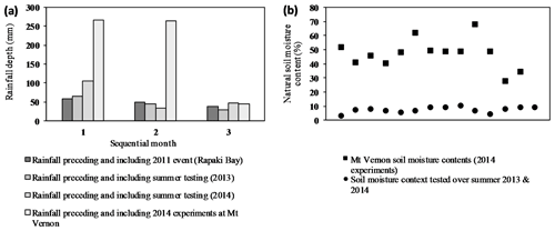
Figure 3(a) Rainfall in the months preceding and during key events of this study: The 2011 earthquake rockfall event at Rapaki Bay, summer soil testing on the Port Hills in 2013 and 2014, and the rockfall experiments conducted at Mt Vernon in 2014. (b) Natural soil moisture contents as tested during the summer testing of 2013 and 2014 (Carey et al., 2014) and as tested during the Mt Vernon rockfall experiments.
Testing conducted by Carey et al. (2014) in January and February 2013 and 2014 (when recorded rainfall for December, January, and February was 65, 46, and 29 and 105, 33, and 48 mm for each year respectively) showed moisture contents ranging from 3.5 % to 11 %. The Rapaki Bay rockfalls occurred during typical dry summer conditions, when rainfall totals of 58, 50, and 38 mm were recorded for December, January, and February, respectively (Fig. 3a and b).
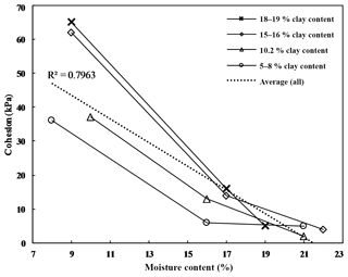
Our direct shear testing of loess samples showed a low moisture content (< 10 %) of the loess resulted in high cohesion (> 35 kPa) for all clay content variations (Fig. 4). Increased moisture content correlated with decreased cohesion; samples with 16 %–17 % moisture displayed cohesion of 6–16 kPa for all clay contents. Moisture contents of > 19 %, above the liquid limit of the soil, displayed < 5 kPa for all percentages of clay contents tested. The spread of the cohesion data is large (±14.5 kPa) for varying clay contents at lower moisture contents, noticeable (±5 kPa) for intermediate moisture content, and low (±1.5 kPa) for high moisture content. High clay contents correspond to higher cohesion values at low and intermediate moisture content, but the effect of clay content is negligible at high moisture contents.
5.2 Impact scarring
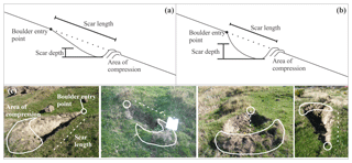
Mapped impact scars in the soil display a wedge-like form, with a clear boulder penetration point at the upslope end and a widening outwards and downslope and an area of compression (where soil has been compacted and pushed up) with some excavated and overturned soil on the downslope end (Fig. 6). Impact scar dimensions at both sites when compared (P=0.035) showed variation in minimum, average, and maximum depth : length ratio: 0.05, 0.29, and 0.4 at Rapaki Bay and 0.125, 0.22, and 0.43 at Mt Vernon respectively (Fig. 5). Although both data sets display similar maximum depth : length ratios, the distribution of the values within the Mt Vernon data set (wet conditions) generally shows a higher depth : length ratio. Scars that show a greater depth : length ratio are a result of impact of boulders which achieve depth in a shorter space during slippage/contact with the ground (Fig. 6a and b). The Rapaki Bay impact scars show a generally lower depth : length ratio, indicative of shallower slippage through the soil during contact with the ground.
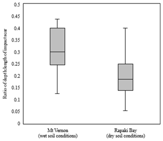
Figure 5Depth vs. length of impact scars measured at Rapaki Bay (n=140) in dry soil conditions and Mt Vernon (n=19) in wet soil conditions. P=0.025.
5.3 Modelling
Modelling was performed at Rapaki Bay to ensure that results were the same/similar following RAMMS updates since the publication of the original calibration (Borella et al., 2015). The RAMMS simulation of boulders at Rapaki Bay still compares favourably with the runout envelope of mapped boulders (Fig. 7). Mapped and simulated boulder distribution within the envelope was compared: the largest proportion of boulders from both data sets were deposited in the upper slope (33∘ shadow angle) and the middle–lower slope (26∘ shadow angle). Both data sets showed a maximum runout within the 22∘ shadow zone. The distributions of the data sets were both constrained by lateral ridges and a creek at the toe. A large proportion of the boulders from both data sets were channelled into a gully running parallel with the slope direction.
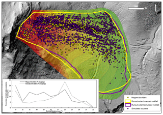
Figure 7Mapped (yellow squares, n=281) and simulated (purple circles, n=5292) rockfall boulder stopping locations within each shadow zone (the zone between projected shadow angles, according to Evans and Hungr, 1993) at Rapaki Bay. Shadow zones are displayed from highest (darkest red is 33∘) to lowest (darkest green is 22∘). Runout extent of mapped (yellow line) and simulated (purple line) boulder populations is compared using envelopes. Inset: Proportion (%) of mapped and simulated boulders stopping within shadow zones.
A RAMMS simulation of Mt Vernon boulder motions was performed using the dry calibration parameters. The runout envelope of the simulated boulders compares unfavourably to the envelope from the experimental rockfall rolling (Fig. 8). Runout of the simulated boulders is 175 m further downslope. The topography is more constrained than Rapaki Bay, with a channelization effect that means lateral dispersion was not large; however the simulated rockfall showed a divergence of boulder paths into a neighbouring gully, behaviour that was not observed during the field experiments.
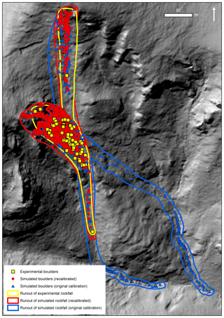
Figure 8Comparison of Mt Vernon experimental rockfall (n=70) runout envelope (yellow line) with simulated rockfall using the initial calibration parameters (blue line = dry) and modified parameters (red line = wet) (boulder n=1800).
An adjustment of parameters from the original values, to reflect wetter soil conditions (Table 4), resulted in a better match between the field experiment and runout simulation envelopes (Fig. 8).
Typical natural moisture contents in the Port Hills range from 10 % to 25 % (Goldwater, 1990). The moisture content at the time of the 22 February 2011 earthquake was likely between 3 % and 11 % (Carey et al., 2014), considered representative of dry soil conditions for the purposes of this study. Soil moisture contents at the time of the Mt Vernon experiments were tested as being between 28 % and 62 %, due to a prolonged period of heavy rainfall in the months preceding the experiments, weather typical of the autumn season, and thus are considered to be representative of wet soil conditions. High moisture content of the Port Hills Loess correlates well with low cohesion/shear strength. By increasing moisture contents past the liquid limit of the soil, cohesion values decrease from as high as 65 to 5 kPa or less for all samples tested, regardless of the recorded proportion of clay particles within the samples. The amount of clay has an influence over the strength (cohesion) of the soil when dry (8 %–11 % moisture), but in wetter conditions (15 %–18 % moisture) its influence is reduced. When wet (moisture contents of 19 %–22 %, above the plastic limit), the influence of clay content is indistinguishable, with cohesion values at or below 5 kPa. This is likely due to the increase in pore pressure reducing the strength of the particle bonds.
Impact scar morphology displays evidence of the impact process: the soil penetration point and ploughing movement of the boulder – pushing soil forward as it slides in a downslope motion, causing compression and shear – reach a maximum friction and rotational momentum, marking the downslope and widened end of the scar. Overturned soil downslope marks the exit point of the boulder from the soil profile. A comparison of depth vs. length of impact scars for the two field sites (Fig. 5) shows that there is (generally) a greater depth relative to length of scarring during the winter when soil is wet, compared to the summer when the soil is dry (although we acknowledge that the scars have not been related to boulder size or impact angle, and the interpretations thereof are limited). As the measured soil moisture content at Mt Vernon was above its liquid limit (measured minimum 28 %), the lower shear strength for the wet soil results in earlier plastic deformation and higher strain on boulder impact. As a result, the boulder achieves higher penetration depth within the soil during the slippage process. When the soil is dry it is harder, and therefore the boulder does not slip as deeply through the soil during contact with the ground, as shown by generally lower depth to length ratios of impact scars at Rapaki Bay in dry soil conditions (Fig. 5). It is likely that the boulder loses less energy to the soil as a result of shallower slippage. As the soil response to impact is mechanically different when the moisture content is different, it follows that the parameterization of the substrate material within the rockfall model should also be altered.
RAMMS modelling at Mt Vernon, using parameters calibrated to the Rapaki Bay data set (dry conditions), shows that runout distance is overestimated when compared with rockfall field runout experiments. Adjustments of some of the RAMMS terrain parameters, to reflect the lowering of shear strength of the loess (evidenced by both the direct shear testing results and measurements of impact scar depth to length ratio), results in a more favourable match between the actual and modelled runout. All impact scars recorded during mapping at Rapaki Bay and following rockfall experiments conducted at Mt Vernon show a morphology that confirms the efficacy of the slippage model component in RAMMS (and parameterization thereof), and adjustments to the parameters set to reflect changes in impact dynamics under different soil moisture contents (and therefore strength) are valid. RAMMS is the only rockfall runout model currently available that represents boulder–substrate interaction as slippage, with parameterization thereof. Other runout models may require a different approach to representing the change in soil conditions and its effect on the boulder runout, for example, reduction of the traditional coefficient of restitution for wet soil conditions, to represent the increased damping effect the soil has on the boulder during impact.
We propose that under rapid-loading stress conditions (boulder impact), the proportion of recoverable (elastic) deformation is lower and irrecoverable (inelastic) deformation is higher for wet soil than for dry soil. We also propose that in a soil impact scenario, the irrecoverable stress proportion of the soil deformation in wet conditions results in a greater impact depth in the soil by the boulder due to lower stiffness, as noted by the increase in impact scar depth in wet conditions. Furthermore, the greater plastic or viscous soil deformation under boulder impact loading in wet conditions results in a greater proportion of energy lost to the soil. As boulder motion in rockfall events ends when the kinetic energy is completely dissipated, the runout distance of the boulder will be shorter under wet soil conditions compared to the same soil under dry conditions.
By increasing the duration of slip through soil on impact in RAMMS, the decreased shear strength of the soil under wet conditions is represented. The runout of dry vs. wet soil modelling shows that by adjusting the parameters to suit the ground conditions, the actual runout is better represented. Dry soil will produce greater boulder runout distances than the same soil when wet. For hazard analysis purposes, practitioners should consider their terrain representation under different moisture conditions within rockfall models to ensure the maximum possible rockfall runout and hence damage potential has been accounted for.
The method of linking direct shear test results with soil performance under boulder impact is limiting, as the method of compacting disturbed soil during shear testing means that the internal structure of the soil is lost due to the remoulding. The strength values are therefore not wholly representative of in situ conditions, and greater accuracy in the strength properties of the loess would be achieved by performing similar tests on undisturbed samples.
Furthermore, representing soil conditions as only either dry or wet is a crude representation of actual conditions. Realistically the mechanics of soil behaviour will change continually with incremental increases in moisture content, and we recommend this contribution is further developed to explore the effect a range of moisture conditions will have on rockfall runout. In the future rockfall model parameterization should be fine-tuned to a range of soil properties.
Rockfall modelling using terrain parameters calibrated to rockfall events during dry loess soil conditions over-simulates runout distance for rockfall events in wet conditions. Under wet conditions loess soil has a lower shear strength, and depth of boulder penetration at impact during a rockfall event will be greater, resulting in a higher damping effect to the boulder and therefore a shorter overall runout distance. Rockfall model users should take soil conditions into account to ensure they have allowed for the worst-case runout distance when simulating rockfall events for hazard prediction purposes.
The data used in this study are not publicly available; however the lead author can be contacted for acquisition of select data (louise.m.vick@uit.no).
LMV conceptualized and conducted the study, analysed the data, and wrote and edited all drafts. VZ contributed to the conceptualization of the study as well as to the formal analysis and writing of the original draft. CW conducted investigations and analysis and contributed to review and editing of the later draft. CM and TD procured funding for the PhD project, supervised the project, and contributed to validation, reviewing, and editing.
The authors declare that they have no conflict of interest.
This project was undertaken at the University of Canterbury. Mt Vernon experiment costs were covered by Bell Geoconsulting Ltd, with a contribution from Solutions 2 Access. The publication charges for this article have been funded by a grant from the publication fund of UiT The Arctic University of Norway. We would like to acknowledge Marlène Villeneuve for help with editing, James Glover for assistance with the experiments and editing, Marc Christen and the SLF Davos for assistance with RAMMS and providing multiple free licences, and Ellery Daines for edits and suggestions. We also thank the editor and the reviewers whose careful critique and valid suggestions have greatly improved the paper.
This research has been supported by the Natural Hazards Research Platform (grant no. C05X0907). The publication charges for this article have been funded by a grant from the publication fund of UiT The Arctic University of Norway (project 551011).
This paper was edited by Paola Reichenbach and reviewed by Mark Eggers and Greg Stock.
Azzoni, A. and de Freitas, M. H.: Experimentally gained parameters, decisive for rock fall analysis, Rock Mech. Rock Eng., 28, 111–124, https://doi.org/10.1007/BF01020064, 1995.
Bannister, S. and Gledhill, K.: Evolution of the 2010–2012 Canterbury earthquake sequence, New Zeal. J. Geol. Geop., 55, 295–304, https://doi.org/10.1080/00288306.2012.680475, 2012.
Bartelt, P., Bieler, C., Bühler, Y., Christen, M., Christen, M., Dreier, L., Gerber, W., Glover, J., Schneider, M., Glocker, C., Leine, R., and Schweizer, A.: RAMMS::ROCKFALL User Manual v1.6., available at: http://ramms.slf.ch/ramms/downloads/RAMMS_ROCK_Manual.pdf (last access: 11 January 2019), 2016.
Beavan, J., Fielding, E., Motagh, M., Samsonov, S., and Donnelly, N.: Fault Location and Slip Distribution of the 22 February 2011 Mw 6.2 Christchurch, New Zealand, Earthquake from Geodetic Data, Seismol. Res. Lett., 82, 789–799, https://doi.org/10.1785/gssrl.82.6.789, 2011.
Bell, D. H. and Crampton, N. A.: Panel report: Engineering geological evaluation of tunnelling conditions, Lyttelton-Woolston LPG Project, Christchurch, New Zealand, in 5th International Congress of the International Association of Engineering Geology, AA Balkema, Buenos Aires, 2485–2502, 1986.
Bell, D. H. and Trangmar, B. B.: Regolith materials and erosion processes on the Port Hills, Christchurch, New Zealand, in 5th International Conference & Field Workshop on Landslides, 93–105, 1987.
Borella, J. W., Quigley, M., and Vick, L.: Anthropocene rockfalls travel farther than prehistoric predecessors, Sci. Adv., 2, 1–11, https://doi.org/10.1126/sciadv.1600969, 2016.
Bozzolo, D. and Pamini, R.: Simulation of Rock Falls down a Valley Side, Acta Mech., 63, 113–130, 1986.
Brideau, M., Massey, C., Archibald, G., and Jaboyedoff, M.: Photogrammetry and LiDAR investigation of the cliffs associated with the seismically triggered rockfalls during the February and June 2011 Christchurch, Landslides Eng. Sloped Prot. Soc. through Improv. Underst., 1179–1185, 2012.
Brown, L. J. and Weeber, J. H.: Geology of the Christchurch urban area, Intitute of Geological and Nuclear Sciences, Lower Hutt, New Zealand, 1992.
Carey, J. M., Misra, S., Bruce, Z. R., and Barker, P.: Canterbury Earthquakes 2010/11 Port Hills Slope Stability: Laboratory Testing Factual Report, GNS Sci. Consult. Rep. 2014/53, 2014.
Carey, J. M., McSaveney, M. J., and Petley, D. N.: Dynamic liquefaction of shear zones in intact loess during simulated earthquake loading, Landslides, 14, 789–804, https://doi.org/10.1007/s10346-016-0746-y, 2017.
Chau, K. T., Wong, R. H. C., and Lee, C. F.: Rockfall problems in Hong Kong and some new experimental results for coefficients of restitution, Int. J. Rock Mech. Min. Sci., 35, 662–663, https://doi.org/10.1016/S0148-9062(98)00023-0, 1998.
Claridge, G. and Campbell, I.: Loess sources and eolian deposits in Antarctica, in: Loess: Its distribution, Geology and Soils, edited by: Eden, D. N. and Furkert, R. J., Rotterdam, Balkema, Palmerston North, New Zealand, 33–45, 1987.
Cousins, J. and McVerry, G.: Overview of strong motion data from the Darfield earthquake, Bull. New Zeal. Soc. Earthq. Eng., 43, 222–227, 2010.
Davies, T. R.: Fluvial Processes in Proglacial Environments, in: Treatise on Geomorphology, edited by: Shroder, J., Academic Press, p. 6386, 2013.
Della Pasqua, F., Massey, C., Lukovic, B., Ries, W., Archibald, G., and Heron, D.: Canterbury Earthquakes 2010/11 Port Hills Slope Stability: Risk assessment for Maffeys Road, 112 pp., 2014.
Derbyshire, E. and Mellors, T. W.: Geological and geotechnical characteristics of some loess and loessic soils from China and Britain: A comparison, Eng. Geol., 25, 135–175, https://doi.org/10.1016/0013-7952(88)90024-5, 1988.
Dorren, L. K. A.: A review of rockfall mechanics and modelling approaches, Prog. Phys. Geogr., 27, 69–87, https://doi.org/10.1191/0309133303pp359ra, 2003.
Dorren, L. K. A., Berger, F., le Hir, C., Mermin, E., and Tardif, P.: Mechanisms, effects and management implications of rockfall in forests, Forest Ecol. Manag., 215, 183–195, https://doi.org/10.1016/j.foreco.2005.05.012, 2005.
Evans, S. G. and Hungr, O.: The assessment of rockfall hazard at the base of talus slopes, Can. Geotech. J., 30, 620–636, https://doi.org/10.1139/t93-054, 1993.
Ferrari, F., Giani, G. P., and Apuani, T.: Towards the comprehension of rockfall motion, with the aid of in situ tests, in International Conference on Vajont – 1963–2013 – Thoughts and analyses after 50 years since the catastrophic landslide, Vol. 6, Italian Journal of Engineering Geology and Environment, Padua, 163–171, 2013.
Fry, B., Benites, R., Reyners, M., Holden, C., Kaiser, A., Bannister, S., Gerstenberger, M., Williams, C., Ristau, J., and Beavan, J.: Strong shaking in recent New Zealand earthquakes, Eos (Washington DC), 92, 349–351, https://doi.org/10.1029/2011EO410001, 2011a.
Fry, B., Benites, R., and Kaiser, A.: The Character of Accelerations in the Mw 6.2 Christchurch Earthquake, Seismol. Res. Lett., 82, 846–852, https://doi.org/10.1785/gssrl.82.6.846, 2011b.
Gao, G.: Formation and development of the structure of collapsing loess in China, Eng. Geol., 25, 235–245, https://doi.org/10.1016/0013-7952(88)90029-4, 1988.
Giani, G. P., Giacomini, A., Migliazza, M., and Segalini, A.: Experimental and theoretical studies to improve rock fall analysis and protection work design, Rock Mech. Rock Eng., 37, 369–389, https://doi.org/10.1007/s00603-004-0027-2, 2004.
Glover, J.: Rock-shape and its role in rockfall dynamics, Durham University, available at: http://etheses.dur.ac.uk/10968/ (last access: 11 January 2019), 2015.
Goldwater, S.: Slope failure in loess: a detailed investigation, Allandale, Banks Peninsula, University of Cantebury, available at: http://hdl.handle.net/10092/9378 (last access: 11 January 2019), 1990.
Griffiths, E.: Loess of Banks Peninsula, New Zeal. J. Geol. Geop., 16, 657–675, https://doi.org/10.1080/00288306.1973.10431388, 1973.
Hampton, S. J. and Cole, J. W.: Lyttelton Volcano, Banks Peninsula, New Zealand: Primary volcanic landforms and eruptive centre identification, Geomorphology, 104, 284–298, https://doi.org/10.1016/j.geomorph.2008.09.005, 2009.
Hampton, S. J., Cole, J. W., and Bell, D. H.: Syn-eruptive alluvial and fluvial volcanogenic systems within an eroding Miocene volcanic complex, Lyttelton Volcano, Bank Peninsula, New Zealand, New Zeal. J. Geol. Geop., 55, 53–66, https://doi.org/10.1080/00288306.2011.632424, 2012.
Holden, C.: Kinematic Source Model of the 22 February 2011 Mw 6.2 Christchurch Earthquake Using Strong Motion Data, Seismol. Res. Lett., 82, 783–788, https://doi.org/10.1785/gssrl.82.6.783, 2011.
Hughes, T. J.: A Detailed Study of Banks Peninsula Loess Shear Strength, University of Canterbury, available at: http://hdl.handle.net/10092/10021 (last access: 11 January 2019), 2002.
Jowett, T. W. D.: An Investigation of the Geotechnical Properties of Loess from Canterbury and Marlborough, University of Canterbury, available at: http://hdl.handle.net/10092/7580 (last access: 11 January 2019), 1995.
Kaiser, A., Holden, C., Beavan, J., Beetham, D., Benites, R., Celentano, A., Collett, D., Cousins, J., Cubrinovski, M., Dellow, G., Denys, P., Ficlding, E., Fry, B., Gerstenberger, M., Langridge, R., Massey, C., Motagh, M., Pondard, N., McVerry, G., Ristau, J., Stirling, M., Thomas, J., Uma, S. R., and Zhao, J.: The Mw6.2 Christchurch earthquake of February 2011: Preliminary report, New Zeal. J. Geol. Geop., 55, 67–90, https://doi.org/10.1080/00288306.2011.641182, 2012.
Keefer, D. K.: Landslide caused by earthquakes, GSA Bull., 95, 406–421, 1984.
Kie, T. T.: Fundamental properties of loess from Northwestern China, Eng. Geol., 25, 103–122, https://doi.org/10.1016/0013-7952(88)90022-1, 1988.
Leine, R., Schweizer, A., Christen, M., Glover, J., Bartelt, P., and Gerber, W.: Simulation of rockfall trajectories with consideration of rock shape, Multibody Syst. Dyn., 32, 1–31, 2013.
Lutenegger, A. J. and Hallberg, G. R.: Stability of loess, Eng. Geol., 25, 247–261, https://doi.org/10.1016/0013-7952(88)90030-0, 1988.
Massey, C., Della-Pasqua, F., Lukovic, B., Yetton, M., Archibald, G., and Ries, W.: Canterbury earthquakes 2010/11 Port Hills Slope Stability: Risk assessment for Cliff Street, GNS Sci. Consult. Rep., (2014/73), 1–190, 2014a.
Massey, C., McSaveney, M., Taig, T., Richards, L., Litchfield, N., Rhoades, D., McVerry, G., Lukovic, B., Heron, D., Ries, W., and Van Dissen, R.: Determining rockfall risk in Christchurch using rockfalls triggered by the 2010/2011 Canterbury earthquake sequence, New Zealand, Earthq. Spectra, 30, 155–181, https://doi.org/10.1193/021413EQS026M, 2014b.
Mcdowell, B. J.: Site investigations for residential development on the Port Hills, Christchurch, University of Canterbury, available at: http://hdl.handle.net/10092/5436 (last access: 11 January 2019), 1989.
Mukhtar, J.-A. S.: Engineering Geological and Geotechnical Characterisation of Selected Port Hills Lavas, University of Canterbury, available at: https://ir.canterbury.ac.nz/handle/10092/9971 (last access: 11 January 2019), 2014.
Peng, B.: Rockfall Trajectory Analysis – Parameter Determination and Application, University of Canterbury, available at: http://hdl.handle.net/10092/5802 (last access: 11 January 2019), 2000.
Tehrani, B. H.: Chemical Stabilisation of Whaka Terrace Loess, Christchurch, University of Canterbury, available at: http://hdl.handle.net/10092/6705 (last access: 11 January 2019), 1988.
Vick, L. M.: Evaluation of field data and 3D modelling for rockfall hazard assessment, University of Canterbury, available at: http://hdl.handle.net/10092/10845 (last access: 11 January 2019), 2015.
Volkwein, A., Schellenberg, K., Labiouse, V., Agliardi, F., Berger, F., Bourrier, F., Dorren, L. K. A., Gerber, W., and Jaboyedoff, M.: Rockfall characterisation and structural protection – A review, Nat. Hazards Earth Syst. Sci., 11, 2617–2651, https://doi.org/10.5194/nhess-11-2617-2011, 2011.
Volkwein, A., Brügger, L., Gees, F., Gerber, W., Krummenacher, B., Kummer, P., Lardon, J., and Sutter, T.: Repetitive Rockfall Trajectory Testing, Geosciences, 8, 1–27, https://doi.org/10.3390/geosciences8030088, 2018.
White, C. S.: Earthqauke induced fissuring in Banks Peninsula loessial soils: A geotechnical investigation of the Ramahana Road Fissure trace, University of Canterbury, available at: http://hdl.handle.net/10092/11997 (last access: 11 January 2019), 2016.
Wood, P., Robins, P., and Hare, J.: Preliminary observations of the 2010 darfield (Canterbury) Earthquakes: An introduction, Bull. New Zeal. Soc. Earthq. Eng., 43, 3–6, 2010.
Wyllie, D.: Rock Fall Engineering, 1st Edn., Taylor & Francis Group, Boca Raton, 270 pp., 2014.
Wyllie, D. and Mah, C.: Rock Slope Engineering, 4th Edn., Spon Press, New York, USA, 456 pp., 2004.


