the Creative Commons Attribution 3.0 License.
the Creative Commons Attribution 3.0 License.
Mechanism of groundwater inrush hazard caused by solution mining in a multilayered rock-salt-mining area: a case study in Tongbai, China
Tingting Shi
Zhihua Chen
Liu Xiang
Shaopeng Xiang
Muyi Yang
The solution mining of salt mineral resources may contaminate groundwater and lead to water inrush out of the ground due to brine leakage. Through the example of a serious groundwater inrush hazard in a large salt-mining area in Tongbai County, China, this study mainly aims to analyse the source and channel of the inrushing water. The mining area has three different types of ore beds including trona (trisodium hydrogendicarbonate dihydrate, also sodium sesquicarbonate dihydrate, with the formula Na2CO3 × NaHCO3 × 2H2O, it is a non-marine evaporite mineral), glauber (sodium sulfate, it is the inorganic compound with the formula Na2SO4 as well as several related hydrates) and gypsum (a soft sulfate mineral composed of calcium sulfate dihydrate, with chemical formula CaSO4 × 2H2O). Based on characterisation of the geological and hydrogeological conditions, the hydrochemical data of the groundwater at different points and depths were used to analyse the pollution source and the pollutant component from single or mixed brine by using physical–chemical reaction principle analysis and hydrogeochemical simulation method. Finally, a possible brine leakage connecting the channel to the ground was discussed from both the geological and artificial perspectives. The results reveal that the brine from the trona mine is the major pollution source; there is a NW–SE fissure zone controlled by the geological structure that provides the main channels through which brine can flow into the aquifer around the water inrush regions, with a large number of waste gypsum exploration boreholes channelling the polluted groundwater inrush out of the ground. This research can be a valuable reference for avoiding and assessing groundwater inrush hazards in similar rock-salt-mining areas, which is advantageous for both groundwater quality protection and public health.
- Article
(5672 KB) - Full-text XML
- BibTeX
- EndNote


Solution mining is commonly used in salt mine exploitation, as salts are soluble in water. In this method, high-pressure and -temperature water with low salinity is injected into a mineral deposit through production wells to dissolve the mineral salts. After being drawn from the wells, the soluble salt is purified and processed further. However, the high-pressure and -temperature water used in this process not only dissolves minerals but also cause fractures in the strata, which usually results in hazards, such as brine leakage or groundwater inrush. In this situation, drinking groundwater for the public is normally polluted following groundwater inrush, thus creating a hazard and threatening the health of local residents.
Many scholars (Clark and Fritz, 1997; Liu et al., 2015; Wu et al., 2016) have studied groundwater inrush hazards in both coal and metal mines, and some adopted methods are as follows: the use of water level/temperature criterion (Yuan and Gui, 2005; Ma and Qian, 2014), stochastic simulation (Fernandez-Galvez et al., 2007), numerical simulation (Liu et al., 2009; Kang et al., 2012; Shao et al., 2013; Houben, et al., 2017), water chemical analysis (isotope analysis, water quality type correlation analysis) (Robins, 2002; Fernandez et al., 2005; Hu et al., 2010; Cobbina et al., 2015; Lee et al., 2016; LeDoux et al., 2016), multivariate statistics (discriminant analysis, clustering analysis) (Chen and Li, 2009; Lu, 2012), fractional advection dispersion equations (Ramadas et al., 2015) and non-linear analysis (fuzzy mathematics, grey correlation analysis, etc.) (Hao et al., 2010; Gao, 2012). However, due to the particularity of the solution-mining method and the complex chemical–physical reactions during the high-pressure and -temperature mining process, research regarding solution mining were mainly focused on mining techniques (Jiang and Jiang, 2004; Kotwica, 2008; Namin et al., 2009), mining cavity stability analysis and sinkhole problems (Staudtmeister and Rokahr, 1997; Bonetto et al., 2008; Ezersky et al., 2009; Goldscheider and Bechtel, 2009; Closson and Abou Karaki, 2009; Vigna et al., 2010; Frumkin et al., 2011; Ezersky and Frumkin, 2013; Qiu, 2011; Blachowski et al., 2014) and geohazards, particularly in karst areas due to man-made underground caving (Waltham and Fookes 2003; Parise and Gunn 2007; Zhou and Beck 2011; Parise and Lollino 2011; Lollino et al., 2013; Gutierrez et al., 2014; Parise et al., 2015) but rarely on source and channel analysis of water inrush in a solution-mining accident.
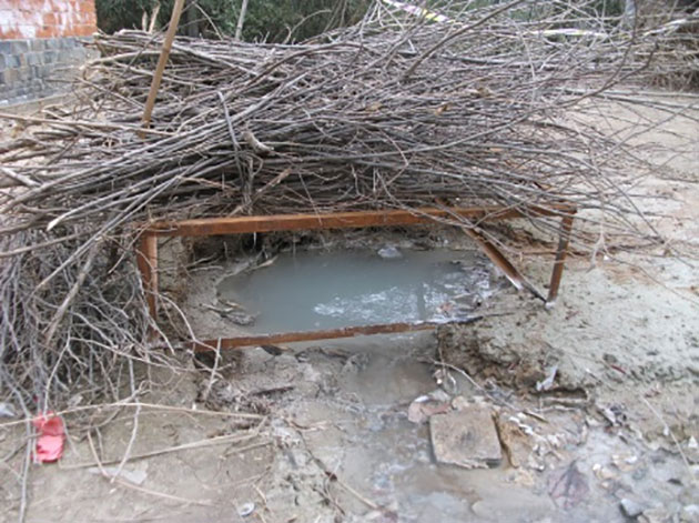
Figure 1One of the long-term (longer than 2 years) groundwater inrush points with stable discharge (Y3).
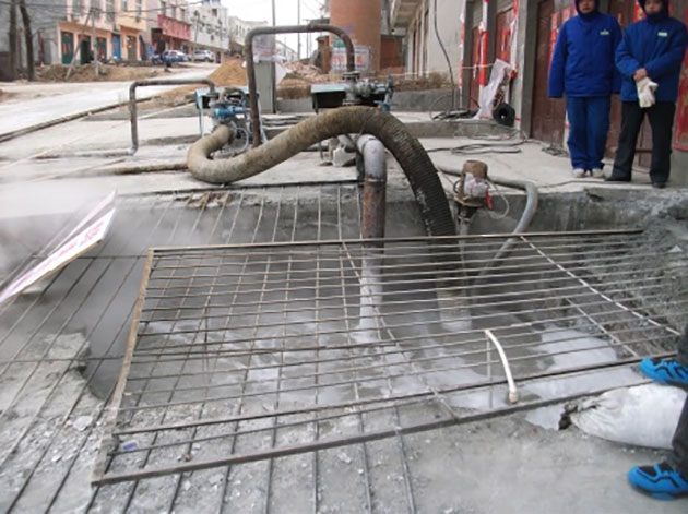
Figure 2The sudden groundwater inrush point (Y5). The high-temperature inrush groundwater was being pumped after the ground was broken.
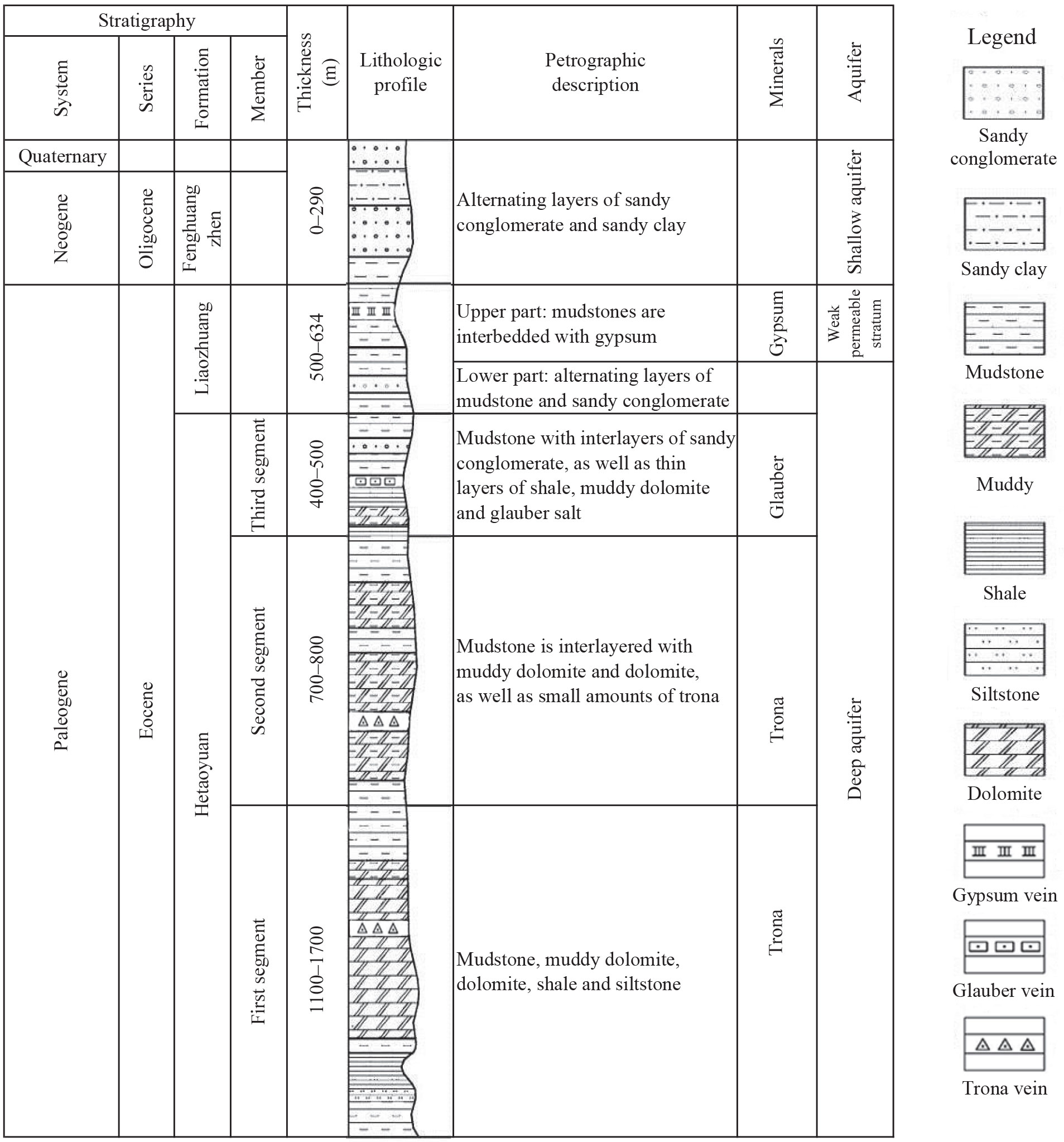
Figure 3Information about strata, lithology, aquifers and buried positions of each ore bed in the mining area.
The rock-salt-mining area in this study is located in Tongbai County, Henan Province, China. This mining area has the second largest trona reserves in the world, while its glauber salt reserves reach 45 million tons. Since trona and glauber salt were put into production in 1990 with single- and double-well convection mining as the main producing method, five inrush points appeared in the town of Anpeng, Tongbai County, from June 2011 to May 2013. Among these five inrush points, four (Y1–Y4) were long-term (longer than 2 years) inrush points with stable discharge, while one (Y5) was a sudden inrush point (as shown in Figs. 1 and 2). Almost 200 m3 of mud and sediment erupted out of the ground at the Y5 point on 1 February 2013. The area of the inrush point was ∼ 4 m2 and the average water inflow was 20–30 m3 d−1, while the greatest inflow reached 200 m3 d−1. The water inrush lasted for approximately 3 months. During the Y5 inrush accident, according to the field investigation, a trona production well named “S02”, located 200 m far from the inrush point, broke at a depth of 234 m and remained broken for a long period of time. It was repaired on 15 March 2013. During the entire process, the groundwater inrush led to the phenomenon of salinization at the base of many houses in the village and made water in many residents' wells no longer drinkable.
Since the groundwater inrush hazard involved a large geographic area and the inrush source was quite hard to distinguish due to the multilayer distribution of the different ore bodies and the complexity of the water inrush component, a targeted treatment programme to stop the water inrush and mitigate the groundwater pollution were needed urgently in research region. Therefore, the source and channel of the water inrush were taken as the research focus in this study. Furthermore, this research can provide a valuable reference for avoiding and assessing groundwater inrush hazards in similar rock-salt-mining areas, which is advantageous for both groundwater quality protection and public health.
2.1 Geological conditions
The mining area is located in north-western Tongbai County. The landscape is characterised by hollows and ridges, with an elevation ranging from 140 to 200 m above sea level.
The main development period of the research area consists of strata from the Hetaoyuan, Liaozhuang and Fenghuangzhen formations, from the oldest to the youngest. The Hetaoyuan Formation from the Palaeogene consists mainly of dolomite, muddy dolomite, mudstone, dolomitic mudstone, sandy conglomerate and siltstone. The third segment in the Hetaoyuan Formation is composed of thick mudstone interlayered with sandy conglomerate as well as thin layers of shale, muddy dolomite and glauber salt. The second segment is composed of mudstone interlayered with muddy dolomite and dolomite as well as small amount of trona. The first segment consists of mudstone, muddy dolomite, dolomite, shale, siltstone and trona. The upper part of the Liaozhuang Formation from the Palaeogene consists of mudstone interlayered with gypsum, while the lower part consists of alternating layers of mudstone and sandy conglomerate. The Fenghuangzhen Formation from the Neogene and Quaternary periods consists of alternating layers of sandy conglomerate and sandy clay (Shi et al., 2013). Detailed information on strata, lithology, aquifer and the position of different ore beds in the research area is shown in Fig. 3.
According to geologic references and field investigation, in the north-eastern mining area, a hidden east–west-oriented fault develops at the bottom of the first segment of the Hetaoyuan Formation and another four, hidden, south–north-oriented faults develop at the bottom of the second segment of the Hetaoyuan Formation. These five faults are outside the scope of the trona mine, so they have little effect on the ore bed. A few small-scale hidden faults develop at the bottom of the third segment of the Hetaoyuan Formation, although within the scope of the glauber salt mine, they have little effect on the glauber salt ore bed which is distributed at the top of the first segment of the Hetaoyuan Formation. A hidden east–west-oriented fault is developed at the bottom of the Liaozhuang Formation in the range of the glauber salt mine, but it has little effect on the glauber salt mine because of its small scale.
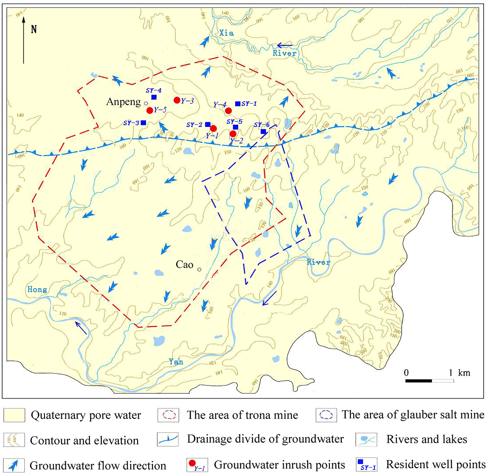
Figure 4Sketched map of hydrogeological conditions and the distribution of groundwater inrush points in the mining area.
2.2 Hydrogeological conditions
The groundwater in the mining area can be divided into pore water in the loose rock mass and bedrock fissure water according to the lithology and hydrogeological features. In the upper part of the Liaozhuang Formation, a mudstone interbedded with gypsum is considered a relatively weak permeable stratum, especially under conditions of high-pressure and -temperature water injection during the mining period. The shallow aquifer contains unconsolidated pore water above this weak permeable stratum, while the deep aquifer contains a bedrock fissure beneath this weak permeable stratum.
The flow direction of the shallow groundwater is controlled by the regional terrain. Taking the underground watershed as the boundary, the groundwater on the southern side of the watershed mainly flows from north-east to south-west with the Yanhong River as the drainage base, while the groundwater on the northern side of the watershed mainly flows from south to north with the Xia River as the drainage base. The deep groundwater is in relatively closed burial conditions, with slow velocity and nearly the same flowing direction as the shallow groundwater. The water inflow of a single well with poor water content is approximately 100 m3 d−1, but it can reach 1000–2000 m3 d−1 if it has rich water content. The annual amplitude of the groundwater level is from 2 to 4 m, while the depth is stable at 2.3–4 m. Residents in Anpeng use groundwater as their drinking water, which comes from wells in the porous aquifer.
Gypsum mainly occurs at the top of the Liaozhuang Formation, glauber salt occurs in the third member of the Hetaoyuan Formation, and the trona occurs at the bottom of the second member of the Hetaoyuan Formation as well as on top of the first member of the Hetaoyuan Formation (Fig. 3). The surrounding rocks of every mineral layer, including mudstone, shale, sandy conglomerate, psammitic rock and dolomite, have sufficient thickness and good water resistance. Therefore, the effect of groundwater on the mineral deposit is minimal in the mining area.
2.3 Distribution and characteristics of the ore body
The three ore bodies overlap in plane distribution, as shown in Fig. 4. The vertical distribution of the ore bodies from deep to shallow is trona (buried depth: 1560.92–2929.53 m), glauber salt (buried depth: 1003.66–1397.58 m) and gypsum (buried depth: 134–338 m). The trona and glauber salt bodies are at least 250 m apart from each other vertically.
The trona has 11 horizontal layers, with an average thickness of 2.11 m. The chemical composition of trona is mainly NaHCO3 (average of 77.06 %) and Na2CO3 (average of 16.33 %) (Wang, 1987). The glauber salt has four layers, with an average thickness of 8.93 m. The dip angle of the ore bed layer is less than 10∘. The average mineral grade is 60.14 %. The main composition of the glauber salt is Na2SO4 (> 90 %) with a small amount of NaCl.
Based on the field investigation results the source of the water inrush was determined by chemical analysis of the water inrush at different sites and times and by analysis of the physical and chemical reaction principles for the different brines combined with the PHREEQC simulation method.
3.1 Sampling and testing
The five groundwater inrush points (Y1∼ Y5) and some shallow groundwater points (resident wells: SY1 ∼ SY6) near the accident site were chosen as groundwater quality sampling points, as shown in Fig. 4. Water from each point was sampled on 9 March 2013.
Water samples were filtered using a 0.45 µm millipore filtration membrane in the field and then filled with a polyethylene bottle which had been soaked in acid and washed with deionised water. Filtered water samples were acidified until they reached pH < 2 by addition of ultrapure HNO3 for the determination of cations; water samples for the determination of anions were not treated.
Elements tested in the laboratory included 26 cations (K+, Na+, Ca2+, Mg2+, Sr2+, etc.) and 5 anions (F−, Cl−, NO, SO, NO. The instrument used for the determination of cations was an inductively coupled plasma atomic emission spectrometer (Agilent ICP-OES 5100), with minimum detection limit at 0.0001 mg L1−. The instrument used for the determination of anions was an ion chromatograph (ICS-1100), and the minimum detection limit was 0.001 mg L1−. CO and HCO were tested according to the “Groundwater quality test method: Determination of carbonate and bicarbonate by hydroxide titration (DZ/T 0064.49–93)”, with a minimum detection limit at 0.01 mg L1−.
In addition, from March to April 2013, at the Y5 and Y3 sites, three water quality automatic recorders (Levelogger gold, Canada) were arranged for water inrush monitoring. Monitoring indicators were temperature, water level and electrical conductivity. The purpose of the monitoring was to fully understand the water quality of the inrush throughout the accident, especially in the process of repairing the well.
3.2 Analysis of the physical and chemical reaction principles in different brine mixing conditions
During the accident, the brine leakage of the trona (2000 m below the ground) or glauber salt (1000 m below the ground) might flow through the gypsum deposit (200–400 m below the ground), which is comprised primarily of CaSO4 and cause physical and chemical reactions while it rushes out of the ground. Thus, the formation of the chemistry component in water inrush might be from glauber brine, trona brine or a mixture of the two flowing through the gypsum layer with accompanying physical and chemical reactions. To provide a basis for further analysis of the water inrush source, the physical solubility of the gypsum and the reaction were analysed when the glauber salt brine, the trona brine or a mixture of the two flowed through the gypsum deposits.
3.2.1 The physical solubility of gypsum (CaSO4)
Gypsum is slightly soluble; when in water, its acidity is apparent. Equation (1) provides the dissolution rate equation of gypsum in water:
where RGypsum is the dissolution rate of gypsum, k1 is the rate constant, Ag is the surface area of gypsum, V is the liquid volume in contact with the gypsum surface, IAP is the product of ion activity, and K is the ion solubility product.
The solubility of gypsum in water reaches a maximum of 0.2097 g/100 g at 40∘. The solubility decreases when the temperature is below or above 40∘. The content of SO and Ca2+ obtained by physical dissolution is very low.
3.2.2 Gypsum (CaSO4) dissolved by glauber salt brine (Na2SO4)
Equations (2) and (3) show the reactions of Na2SO4 and CaSO4 with water.
Because of the common-ion effect, the solubility of the electrolyte will decrease when a strong electrolyte with the same ion is placed into an electrolyte-saturated solution. Thus, the solubility of gypsum will be reduced when glauber salt brine flows through and dissolves the gypsum deposits; the gypsum will be even harder to dissolve in this situation. Thus, if the glauber salt brine flows through the gypsum deposits, the brine characteristic would apparently not change.
3.2.3 The reaction of trona brine or a mixture of trona and glauber salt brine with gypsum
The HCO and CO contents in trona brine or in mixed brine are very high, as are the solution alkalinity and pH. If the reaction kinetics is not taken into account, the pH has little influence on the dissolution of gypsum (Yang, 2003; Xu and Li, 2011). The reaction occurs when the brine with high concentrations of HCO and CO flows through the gypsum deposits. The main chemical reactions are as follows:
In Eq. (4), CaSO4 is slightly soluble, while CaCO3 is insoluble. The reaction easily occurs when an insoluble substance is produced by a slight soluble substance, and the ionic equation is as follows:
The Gibbs free energy (G) is −22.7 kJ mol−1 under the standard state. When G is negative, the reaction, which is endothermic, occurs freely. The reaction is faster at higher temperatures. Equation (5) shows that G is 2102 kJ mol−1 under the standard state. When G is positive, the reaction will not freely occur.
Thus, the reaction shown in Eq. (5) will not occur, but the chemical reaction will still proceed as shown in Eq. (4), when trona brine or mixed brine flow through the gypsum deposits.
3.2.4 The carbonate equilibrium effect during the reaction of different brine
The carbonate equilibrium in the trona brine or in the mixed brine is affected by pH. The carbonate in groundwater exists in three forms: free carbonic acid, bicarbonate and carbonic acid.
In the trona brine (pH > 10), the concentration of HCO is 5–20 times that of the CO concentration, and CO in the brine is dominant in this case. When the trona brine flows through the gypsum, CaSO4 reacts with CO and CaCO3 precipitates. If the concentration of CO in the brine decreases, a reversible reaction will take place and drive the equilibrium to the right. Thus, the reverse reaction will occur when the trona brine flows through the gypsum as follows:
The circular reactions as shown in Eqs. (7) and (8) will occur when mixed brine flows through the gypsum because it has similar properties to the trona brine. Thus, taking the carbonate equilibrium effect into account, the concentrations of HCO and CO will decrease, while SO increases after CaCO3 precipitates.
3.3 Simulation of groundwater inrush source
For further quantitative analysis of the water inrush source and component, the international hydrological and geochemical simulation software PHREEQC was used to simulate the water–rock interaction. The PHREEQC software was developed by the US Geological Survey and is able to calculate geochemical action within a temperature range of 0∼ 300∘ (Wei, 2010).
Based on the deduction that the main water inrush source around Anpeng was trona brine leakage, the simulation method PHREEQC was used and combined with the possible channel of water inrush to establish a conceptual model. Then, the hydrogeochemical simulation of the water–rock interaction was conducted. Subsequently, the mixed ratio of groundwater inrush and shallow groundwater around Anpeng were quantified to better verify the source of the water inrush.
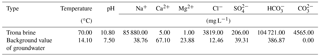
Table 1Initial data on trona brine and background value of groundwater for the PHREEQC simulation.
3.3.1 Conceptual model
Around Anpeng, the trona brine leakage flowed through the specified mineral assemblages and mixed with shallow groundwater in different proportions.
3.3.2 Initial data input
The parameters of the trona brine were taken from the enterprise's production testing data. The parameters of the shallow groundwater were taken from the same aquifer but outside the study area and can basically represent groundwater background values. The specific parameters are shown in Table 1.
3.3.3 Setting of stratum and mineral
The formations from the bottom to the top during the process of the brine leakage flowing into the shallow groundwater and then flowing out of the ground were as follows: the third member of the Hetaoyuan Formation from the Palaeogene, the Liaozhuang Formation and the Fenghuang Formation from the Neogene and Quaternary periods. To simplify the mining area according to the thickness of the rock stratum and the proportion of mineral composition, it can be assumed that the layer through which the trona brine flowed contains Ca-montmorillonite, kaolinite, gypsum, potash feldspar and potash mica.
The main components are as follows: kaolinite is Al4[Si4O10](OH)8, gypsum is CaSO4 × H2O, ca-montmorillonite is (Na, Ca)0.33(Al,Mg)2[Si4O10](OH)2 × nH2O, dolomite is CaMg(CO3)2, potash feldspar is K [AlSi3O8], potash mica is aluminium silicate as K, Al, Mg, Fe and Li.
Table 2Chemical composition of groundwater from the inrush hazard points and surrounding resident wells.
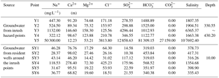
On 9 March 2013, in Anpeng, water samples from five groundwater inrush points and six surrounding water quality monitoring points (resident well) were tested. The results of water chemical composition are shown in Table 2, and the distribution of the sampling points is shown in Fig. 4.
According to the water quality analysis, the brine inrush had a relatively high salinity, with some water inrush samples containing SO4-Na and some containing HCO3-Na. The crystals mainly consisted of NaSO4, Na2CO3 and NaHCO3. The composition of the water inrush and the crystals was the same as that of the high-concentrated ions in the trona brine (Na2CO3, NaHCO3, etc.) and in the glauber salt brine (Na2SO4).
4.1 The source of the water inrush
An automatic water quality recorder was set up at the Y5 inrush point on 4 March 2013. The monitoring lasted from 5 March to 20 March 2013. Thus, the relationship between the inrush points and the S02 well can be assessed according to the correlation of the changes between temperature/electrical conductivity and the concentration of brine during the S02 production well repair period (5 March to 14 March 2013).
The production of glauber ceased during the investigation (2 March to 15 March 2013), so it could be determined how glauber mining affects the water inrush hazard based on a dynamic water quality situation.
4.1.1 The source of water inrush at the Y5 point
After successful repair of the S02 well, the conductivity and temperature of the water inrush decreased significantly. The CO concentration remained at 0 and the HCO concentration decreased to 500 meq L−1, while the SO concentration increased to 600 meq L−1. Subsequently, the concentrations of these three ions were in a state of dynamic balance. The analysis shows that the source of the water inrush at the Y5 point is closely related to the S02 trona well.
In order to ensure whether the glauber brine exists at this point as part of an inrush source, further analysis was performed. The depth of the trona production well rupture was 234 m, and the gypsum deposit was developed at the depth of 134–338 m, so while the leakage of the trona brine flowed through the gypsum deposit, reactions would occur as shown in Eqs. (7) and (8).
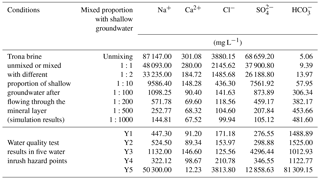
Table 3Simulation results for a mixed proportion of trona brine inrush using the PHREEQC method.
According to the ion milliequivalent concentrations (Ca2+: 0.61; CO: 905.3; HCO: 1332.94; Cl−: 107.43; and SO: 267.89 meq L−1) at the Y5 point, the concentration of Ca2+ was negligible compared to the other main ions. Only the reaction between CO and CaSO4 had to be taken into account because of the large number of CO, high velocity, the short contact time with gypsum and the high temperature. The reaction of CO and CaSO4 would take place at a ratio of 1:1 according to Eq. (7), and three types of water inrush sources could be assumed under this precondition as follows.
The water inrush source was only from the trona brine. The CO and CaSO4 in the brine reacted at a ratio of 1:1, and the SO concentration was equal to the reacted γCO content. Thus, the γCOHCO ratio in the trona brine was equal to the γ(COSOHCO ratio in the water inrush. From this calculation, it could be seen that γ(COSOHCO was equal to 0.88, while γCOHCO ranged between 0.86 and 1.26. The content of γ(COSOHCO was similar to γCOHCO; therefore, the source of the water inrush was exclusively trona brine.
The water inrush source was only from the glauber brine. The γSOHCO ratio in the glauber brine was equal to 1237.8, compared to 0.19 in the water inrush. Therefore, this assumption was incorrect because of the widely varying ratios.
The water inrush source was from a mixed brine of glauber and trona. Assuming that the contribution ratio of the glauber brine was X and that of the trona brine was Y, then . This equation showed that when the contribution ratio of the trona brine was equal to 1, the contribution ratio of the glauber brine was equal to 1.6 × 10⁻⁵, small enough that it can be ignored.
Thus, it could be confirmed that the water inrush source at Y5 was exclusively the leakage of trona brine from the broken S02 well.
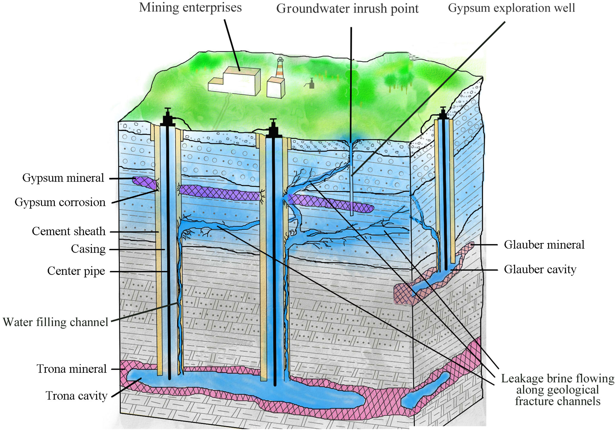
Figure 5Schematic diagram of the source and channel of the groundwater inrush hazard in the multilayered rock-salt-mining area in Tongbai County.
4.1.2 The sources of water inrush at the Y4, Y3, Y2 and Y1 points
The water inrush quantity and the dynamic variation of the concentration of SO and HCO at points Y1–Y4 were not obvious when the S02 well was under repair and all the glauber wells were shut down (from 2 to 15 March). This result shows that the sources of these water inrush points were not due to the underground mining activities of the glauber brine or the rupture of the S02 well but rather to the brine leakage from other trona wells.
4.1.3 Components and mixed proportions of the water inrush
The PHREEQC simulation conditions were assumed to be as follows: (1) the trona brine did not mix with shallow groundwater after flowing through the mineral layer or (2) the trona brine mixed with shallow groundwater in a ratio of 1:2, 1:10, 1:100, 1:200, 1:500, 1:1000 and 1:5000 after flowing through the mineral layer. The simulation results are shown in Table 3.
Table 3 shows that when the trona brine flowed through the bedrock of Hetaoyuan, Liaozhuang, Fenghuangzhen Formation and shallow groundwater successively, the concentrations of Na+, Cl− and SO decreased while the HCO concentration increased with an increasing proportion of shallow groundwater. The Ca2+ concentration decreased at first and then increased.
The ion concentrations at Y5, except for SO, were similar to the ion concentrations in the trona brine. However, at the same time, the HCO concentration was nearly 0 meq L−1. When the trona brine flowed through the layer, it reacted rapidly and poured out of the ground directly because of the high velocity of the water inrush at Y5. Meanwhile, the trona brine was not continuously provided in the simulation. Thus, the concentration of HCO would be near to the concentration of trona brine in reality. Therefore, the trona brine must have a rapid inrush and almost not mix with the shallow groundwater.
The PHREEQC simulation results show that (1) the water inrush source of Y5 was the trona brine almost all from the ruptured S02 well, (2) the water inrush source of Y3 was a mixture of trona brine and groundwater in a ratio of 1:10–1:100, and (3) the water inrush sources of Y4, Y2 and Y1 were a mixture of trona brine and groundwater with ratio of 1:200.
4.2 The channel of the water inrush
4.2.1 Causes of the brine leakage
Trona is produced by either a single well or a double/multiple well convection mining method that is water-soluble (Lin, 1987). The main mining unit consists of a salt cavity and production well. Thus, the instability of the salt cavity and the rupture of the production well are the main possible causes of brine leakage.
(1) Analysis of salt cavity stability
The possibility of salt cavity collapse: Trona is distributed at the bottom of the second member of the Hetaoyuan Formation and in the upper part of the first member of the Hetaoyuan Formation, with developed dolomite strata at the roof and floor. The thick and hard surrounding rock structure determined that the cavity is produced by hydrofracture but it is hard to fill with large-scale fractured channels and can remain intact and stable.
The development of a roof fracture: When a mineral is under exploitation, the surrounding rock in the cavity is under pressure from the inner brine. This pressure is equal to the sum of the water injection pressure and the water column pressure in the production well. The water injection pressure of the trona production well is approximately 10–20 MPa, while the 1560.92–2929.53 m (mineral buried depth) water column pressure is approximately 15.3–28.71 MPa. Thus, the greatest water pressure on the surrounding rock in the cavity is 48.71 MPa. The main lithology of the surrounding rock is dolomite (500 m in thickness and 142.66 MPa in compressive strength), which is nearly 3 times that of the greatest possible water pressure. Therefore, large-scale fractures in the surrounding rock of the trona mineral would be difficult to develop under the effect of sustained water pressure.
(2) Analysis of production well rupture
The phenomenon of brine leakage caused by the S02 well rupture in Anpeng indicates that production well damage is a major cause of brine leakage. The depth of the S02 well rupture is 234 m underground, i.e. in the gypsum deposit, which is strongly hygroscopic. The pressure caused by the water swelling is approximately 0.15 MPa (Li and Zhou, 1996), which may damage the production well and induce brine leakage. The high concentration of SO (> 250 mg L−1) generated by the reaction of brine leakage and gypsum can also corrode the production well and lead to groundwater inrush.
4.2.2 Analysis of water-conducting channel
According to our analysis, the most probable reason for brine leakage in trona is the production well rupture. The leaking brine flows along the water-conducting channel into the shallow aquifer and even pour out of the ground. However, the geological structure in the mining area shows no water-conducting fault development. Thus, the water-conducting channel, that the brine leakage flows along, is probably the structure fissure zone or the abandoned gypsum exploitation well.
Structural fissure is the main type of fissure that occurs in groundwater inrush hazards when using the solution-mining method. The structural fissure is determined by the maximum horizontal principal stress, which is controlled by the tectonic stress field in the mining area. The connection direction of the S02 well and the other water inrush points is NW–SE, the same as that of the structural fissure zone development direction. This indicates that the main water-conducting channel in Anpeng is controlled by the structural fissure zone.
The inrush points in Anpeng are all at the abandoned gypsum exploitation wells, which were not closed properly. Thus, high-pressure cavity water or brine leakage can flow along the structural fissure zone, finally connect with these wells and then pour out of the ground through boreholes. Therefore, the abandoned gypsum exploitation wells are the main channels through which the shallow polluted groundwater flowed out of the ground, as shown in Fig. 5.
This study aimed to investigate the source and channel of the water inrush in a multilayer rock-salt-mining area. To achieve the set objectives, an analysis of geological and hydrogeological conditions, an analysis of physical and chemical reaction principles of different brine, the PHREEQC simulation method, and an analysis of geological and artificial causes of the conducting channel where brine leakage flowed from the damage depth out to the ground were combined.
Long-term solution mining with high-pressure and -temperature water not only dissolves minerals, but also may cause rupture of strata and damage of the production well, which usually results in brine leakage or groundwater inrush. Geological and hydrogeological conditions are the basis which determines the total risk of the groundwater inrush hazard. Physical and chemical reaction principle analysis of different brine and hydrogeochemical simulation of water–rock interaction in different assumed conditions using the PHREEQC simulation method can determine the exact source of the brine leakage as well as identify the mixed proportion of water inrush while the brine flows through the mineral layer. Other than geological reasons, mining techniques such as pressure control of injection water and groundwater quality monitoring of exploitation wells may also determine the risk of a groundwater inrush hazard in a multilayer rock-salt-mining area.
The data are not publicly available, but interested parties can contact the corresponding author.
BZ and TS contributed to data analysis and manuscript writing, ZC proposed the main structure of this study, LX and MY designed and performed the experiments, and SX performed the PHREEQC simulation. All the authors read and approved the final manuscript.
The authors declare that they have no conflict of interest.
This work was partially supported by the Fundamental Research Funds for the
Central Universities, China University of Geosciences (Wuhan) [Grant
Numbers: CUGL100219].
Edited by: Mario Parise
Reviewed by: Marco Vattano and one anonymous referee
Blachowski, J., Milczarek, W., and Stefaniak, P.: Deformation information system for facilitating studies of mining-ground deformations, development, and applications, Nat. Hazards Earth Syst. Sci., 14, 1677–1689, 2014.
Bonetto, S., Fiorucci, A., Fornaro, M., and Vigna, B.: Subsidence hazards connected to quarrying activities in a karst area: the case of the Moncalvo sinkhole event (Piedmont, NW Italy), Est. J. Earth Sci., 57, 125–134, 2008.
Chen, H. J. and Li, X. Bi.: Studies of water source determination method of mine water inrush based on Bayes' multi-group stepwise discriminant analysis theory, Rock and Soil Mechanics, 30, 3655–3659, 2009.
Clark, I. D. and Fritz, P.: Environmental isotopes in hydrogeology, Lewis Publishers, New York, USA, 35–37, 1997.
Closson, D. and Abou Karaki, N.: Salt karst and tectonics: sinkholes development along tension cracks between parallel strike-slip faults, Dead Sea, Jordan, Earth Surf. Proc. Land., 1408–1421, 2009.
Cobbina, S. J., Duwiejuah, A. B., Quansah, R., Obiri, S., and Bakobie, N.: Comparative Assessment of Heavy Metals in Drinking Water Sources in Two Small-Scale Mining Communities in Northern Ghana, Int. J. Environ. Res. Pub. He., 12, 10620–10634, 2015.
Ezersky, M. and Frumkin, A.: Fault – Dissolution front relations and the Dead Sea sinkhole problem, Geomorphology, 201, 35–44, 2013.
Ezersky, M., Legchenko, A., Camerlynck, C., and Al-Zoubi, A.: Identification of sinkhole development mechanism based on a combined geophysical study in Nahal Hever South area (Dead Sea coast of Israel), Environ. Geol., 58, 1123–1141, 2009.
Fernandez, I., Olias, M., Ceron, J. C., and De la Rosa, J.: Application of lead stable isotopes to the Guadiamar Aquifer study after the mine tailings spill in Aznalcollar (SW Spain), Environ. Geol., 47, 197–204, 2005.
Fernandez-Galvez, J., Barahona, E., Iriarte, A., and Mingorance, M.D.: A simple methodology for the evaluation of groundwater pollution risks, Sci. Total Environ., 378, 67–70, 2007.
Frumkin, A., Ezersky, M., Al-Zoubi, A., Akkawi, E., and Abueladas, A.-R.: The Dead Sea sinkhole hazard: Geophysical assessment of salt dissolution and collapse, Geomorphology, 134, 102–117, 2011.
Gao, W. D.: Application of Entropy Fuzzy Discriminating methods in Distinguishing Mine Bursting Water Source, Mining Safety & Environmental Protection, 39, 22–24, 2012.
Goldscheider, N. and Bechtel, T. D.: The housing crises from underground – damage to a historic town by geothermal drillings through anhydrite, Staufen, Germany, Hydrogeol. J., 17, 491–493, 2009.
Gutierrez, F., Parise, M., De, Waele, J., and Jourde, H.: A review on natural and human-induced geohazards and impacts in karst, Earth-Sci. Rev., 138, 61–88, 2014.
Hao, B. B., Li, C., and Wang, C. H.: Application of grey correlation degree in the identification of sources of mine water bursting, China Coal, 36, 20–22, 2010.
Hu, W. W., Ma, Z. Y., Cao, H. D., Liu, F., Li, T., and Dou, H. P.: Application of Isotope and Hydrogeochemical Methods in Distinguishing Mine Bursting Water Source, J. Earth Sci. Environ., 32, 268–271, 2010.
Houben, G. J., Sitnikova, M. A., and Post, V. E. A.: Terrestrial sedimentary pyrites as a potential source of trace metal release to groundwater – A case study from the Emsland, Germany, Appl. Geochem., 76, 99–111, 2017.
Jiang, R. Z. and Jiang, T. X.: Present Development and Prospecting of Hydraulic Fracturing Technology, Oil Drilling & Production Technology, 26, 52–57, 2004.
Kang, X. B., Hu, X. W., and Xie, H. Q.: Numerical simulation on the influence of the groundwater flow field during tunneling, Adv. Mat. Res., 594–597, 1230–1233, 2012.
Kotwica, K.: Scenarios of technological development of roadwavs mining in polish coal mines conditions, Gospod. Surowcami Min., 24, 139–152, 2008.
LeDoux, T. M., Szynkiewicz, A., and Faiia, A. M.: Chemical and isotope compositions of shallowgroundwater in areas impacted by hydraulic fracturing and surface mining in the Central Appalachian Basin, Eastern United States, Appl. Geochem., 71, 73–85, 2016.
Lee, H., Choi, Y., Suh, J., and Lee, S. H.: Mapping Copper and Lead Concentrations at Abandoned Mine Areas Using Element Analysis Data from ICP–AES and Portable XRF Instruments: A Comparative Study, Int. J. Environ. Res. Publ. He., 13, 384, https://doi.org/10.3390/ijerph13040384, 2016.
Li, D. D. and Zhou, Z. A.: Possibility of corrosion failure of concrete shaftwall due to water infiltration, J. China Coal Soc., 21, 158–163, 1996.
Lin, Y. X.: The History of Science & Technology of well salt in China, Sichuan Science and Technology Pres, Chengdu, 1987.
Liu, H., Yang, T., Zhu, W., and Yu, Q.: Numerical analysis of the process of water inrush from the 12th coal floor FANGEZHUANG coal mine in China, Controlling Seismic Hazard and Sustainable Development of Deep Mines: 7th International Symposium on ROCKBURST and Seismicity in Mines (RASIM7), 1&2, 1381–1386, 2009.
Liu, R. Z., Liu, J., Zhang, Z. J., Borthwick, A., and Zhang, K.: Accidental Water Pollution Risk Analysis of Mine Tailings Ponds in Guanting Reservoir Watershed, Zhangjiakou City, China, Int. J. Environ. Res. Publ. He., 12, 15269–15284, 2015.
Lollino, P., Martimucci, V., and Parise, M.: Geological survey and numerical modeling of the potential failure mechanisms of underground caves, Geosystem Engineering, 16, 100–112, 2013.
Lu, J. T.: Recognizing of Mine Water Inrush Sources Based on Principal Components Analysis and Fisher Discrimination Analysis Method, China Safety Science Journal, 22, 109–115, 2012.
Ma, L. and Qian, J. Z.: An approach for quickly identifying water-inrush source of mine based on GIS and groundwater chemistry and temperature, Coal Geology & Exploration, 42, 49–53, 2014.
Namin, F. S., Shahriar, K., Bascetin, A., and Ghodsypour, S. H.: Practical applications from decision-making techniques for selection of suitable mining method in Iran, Gospod. Surowcami Min., 25, 57–77, 2009.
Parise, M. and Gunn, J.: Natural and anthropogenic hazards in karst areas: Recognition, Analysis and Mitigation, Geol. Soc. London, 279, 1–3, 2007.
Parise, M. and Lollino, P.: A preliminary analysis of failure mechanisms in karst and man-made underground caves in Southern Italy, Geomorphology, 134, 132–143, 2011.
Parise, M., Closson, D., Gutierrez, F., and Stevanovic, Z.: Anticipating and managing engineering problems in the complex karst environment, Environ. Earth Sci., 74, 7823–7835, 2015.
Qiu, Z. Y.: Mechanism analysis of surface collapse in the area of solution salt mining, Journal of Safety Science and Technology, 7, 27–31, 2011.
Ramadas, M., Ojha, R., and Govindaraju, R. S.: Current and Future Challenges in Groundwater, II: Water Quality Modeling, J. Hydrol. Eng., 13, 132–140, 2015.
Robins, N. S.: Groundwater quality in Scotland: major ion chemistry of the key groundwater bodies, Sci. Total Environ., 294, 41–56, 2002.
Shao, A. J., Huang, Y., and Meng, Q. X.: Numerical Simulation on Water Invasion of Coal Mine, Appl. Mech. Mater., 316/317, 1112–1117, 2013.
Shi, T. T., Chen, Z. H., and Luo, Z. H.: Mechanism of groundwater bursting in a deep rock salt mine region: a case study of the Anpeng trona and glauber salt mines, China, Environ. Earth Sci., 68, 229–239, 2013.
Staudtmeister, K. and Rokahr, R. B.: Rock Mechanical Design of Storage Caverns For Natural Gas in Rock Salt Mass, Int. J. Rock Mechan. Min. Sci., 34, 3–4, 1997.
Vigna, B., Fiorucci, A., Banzato, C., Forti, P., and De Waele, J.: Hypogene gypsum karst and sinkhole formation at Moncalvo (Asti, Italy), Z. Geomorphol., 54, 285–308, 2010.
Waltham, A. C. And Fookes, P. G.: Engineering classification of karst ground conditions, Q. J. Eng. Geol. Hydroge., 36, 101–118, 2003.
Wang, J. M.: A Preliminary Study on the Characteristics and Conditions of forming Anpeng Trona deposits, Petrol. Explor. Dev., 5, 93–99, 1987.
Wei, Y. N.: Research and Application of Hydro-geochemical Simulation, Journal of Water Resources and Water Engineering, 21, 58–61, 2010.
Wu, Q., Li, B., and Chen, Y.: Vulnerability Assessment of Groundwater Inrush from Underlying Aquifers Based on Variable Weight Model and its Application, Water Resour. Manag., 30, 3331–3345, 2016.
Xu, H. and Li, H. S.: Study on CaSO4 crystallization process and its influential factors, Industrial Water Treatment, 5, 67–69, 2011.
Yang, Y. H.: Gypsum mineral dissolution kinetics, M.D. thesis, China University of Geosciences, Wuhan, China, 2003.
Yuan, W. H. and Gui, H. R.: The Characteristics of Geothermal Temperature and Its Application in Distinguishing the Source of Water in Ren Lou Mine, Journal of Anhui University of Science and Technology (Natural Science), 25, 9–11, 2005.
Zhou, W. and Beck, B. F.: Engineering issues on karst, in: Karst Management, edited by: van Beynen, P., Springer, Dordrecht, 9–45, 2011.