the Creative Commons Attribution 4.0 License.
the Creative Commons Attribution 4.0 License.
 | 26 Feb 2024
Optimization strategy for flexible barrier structures: investigation and back analysis of a rockfall disaster case in southwestern China
Li-Ru Luo
Li-Jun Zhang
Qi Wang
Lin-Xu Liao
Li Peng
Field investigations and back analyses were conducted on a rockfall hazard. The flexible barrier protection system constructed along the roadside was damaged by the rockfall impact and lost its mitigation ability. Vital physical characteristics such as rockfall trajectory and kinetic energy were presumed based on the data from the aerial survey and the slope digital model. A numerical model, including slope, rockfalls, and flexible barrier, was created and thus the impacting process was reproduced. It demonstrates that the impact kinetic energy of the rockfall is only around 40 % of its design protection energy. The improper connections of members are the leading causes of damage, which prevent the flexible barrier from producing significant deformation and reduce its capacity to absorb impact force. The damage can be avoided by changing the connections of the members to improve the ability of the nets and ropes to slide and deform. The calculation results indicate that the impact resistance of the optimized model is 3 times better than the actual project. The findings can be used as a guide when designing a flexible protection system that performs better.
- Article
(22281 KB) - Full-text XML
- BibTeX
- EndNote


Flexible protection systems have been widely employed in transportation, land, mineral, and energy sectors, among others, to prevent and control geological disasters on slopes. The flexible barrier, one of the structural variations of the flexible protection system (Volkwein et al., 2011; Gentilini et al., 2012; Shi et al., 2013; Luo et al., 2022), is particularly well known for its effectiveness as a defence against high-energy impact hazards such as rockfalls, debris flows, mudslides, and avalanches (Peila and Ronco, 2009; Rorem et al., 2013; Kwan et al., 2014). The flexible barrier is a structural system made up of the supporting part, the intercepting part, the connecting part, the energy dissipation part, and the anchoring part. It protects by absorbing the kinetic energy of impact from the disaster through the system's significant inelastic deformation (Yu et al., 2018a; Volkwein et al., 2019; Ferrero et al., 2015; Jiang et al., 2020). Some products have passed the 10 000 kJ impact test (Geobrugg, 2017). In actual engineering, however, the flexible barrier is frequently damaged even if the impact energy is lower than the design protection energy. It cannot provide the desired level of protection. The primary cause of this appearance is the disparity between the idealized test conditions and the variety of actual engineering conditions, such as impact effects, system installation forms, and component connection relationships, which results in the decreased reliability of mitigation measures in practical applications. To fully utilize the protective capabilities of flexible barriers, it is crucial to comprehend how these aspects affect the barriers.
Most current research focuses on the mechanical behaviour and damage mechanisms of flexible nets and anchors in controlled laboratory settings (Spadari et al., 2012; Wang et al., 2013). Apart from research on the complexity, only few studies have been conducted on the failure and damage mechanisms of flexible barriers in actual engineering environments. Margreth and Roth (2008) found that the anchor ropes and steel column bases were the most susceptible components of the flexible barrier applied for avalanche protection. According to the analysis by Kwan et al. (2014) of a flexible barrier damaged by debris flow impact, the faulty connection of the protective structure caused the support posts to buckle, and they suggested an optimization strategy. In regard to rockfall impact, some researchers investigated 15 flexible barrier projects damaged by rockfall. These studies clarified that the flexible rockfall barrier primarily experienced five types of damage, including support post instability, post foot damage, steel wire rope breakage, anchor pull-out, and component corrosion (Zhao et al., 2016; Lei and Luo, 2021; Yu et al., 2019; Liu, 2020). Among them, Yu et al. (2019) and Zhao et al. (2016) in particular studied the mechanisms and optimized countermeasures for support post instability and steel wire rope breakage. In actual projects, the impact damage effect of rockfall on the flexible barrier is highly random, and thus it is difficult to fully consider these damage effects in the forward design method commonly used. Therefore, it is necessary to conduct a back analysis to thoroughly research the damage mechanism and performance improvement countermeasures for flexible barrier projects. It is of great significance to improve the reliability of mitigation measures design.
This paper reports on a flexible rockfall barrier that was damaged by rockfall impact on the road leading to the Jiguanshan National Forest Park in Chengdu, Sichuan Province, China. A series of field investigations were conducted to identify the trajectories of the rockfalls and gather information on the rockfalls and flexible barrier damage. A digital slope model was created based on an unmanned aerial vehicle (UAV) survey. Essential physical characteristics, including the rockfall trajectory and impact kinetic energy, were assumed. Combining the investigation information, a finite element (FE) model containing a part of the slope, the rockfalls, and the flexible rockfall barrier was established. A back analysis of the dynamic process of rockfalls impacting the protection system was then performed to replicate the damage evolution process of the protection system and to reveal the damage mechanism of the actual protection project. Finally, optimized design strategies were proposed with the same material types and specifications used in the existing project. Compared with the back analysis model, the optimized model avoids the damage phenomenon found by the investigation and improves protection capability by at least 3-fold. The research results of this paper can provide a reference for improving the reliability of flexible rockfall barriers.
2.1 Description of the study site in Jiguanshan
As shown in Fig. 1a, Jiguanshan National Forest Park is situated in Chongzhou, southwest of Chengdu – with its back toward Longmen Mountain and its front facing Chengdu Plain – and in the middle south section of the Longmen Mountain structural belt, with complex structural conditions. The southeast of Chongzhou is plain, the centre and western regions of the southeast are hilly, and the broad western areas are covered with low mountain and high mountain landforms. The faults and folds in the low mountain regions of the west cause the rock mass to be broken and cleavage fissure to develop, deeply cut the terrain, and result in a significant relative height difference (Yang et al., 2023). The authors investigated multiple cave-in rockfall disasters that damaged the flexible barriers along the Jiguanshan Road leading to the Jiguanshan National Forest Park in mid-November 2020. Three flexible rockfall barrier projects with similar structural forms experienced system overturning and damage from buckling steel columns, with the most common buckling forms being “C”-shaped compression buckling and “S”-shaped bending and torsion buckling (Figs. 1a and 2). This paper provides a detailed investigation and analysis of one of the three disaster sites where the intercepted rockfalls were still inside the protection system, so that more information could be gathered at that site (Figs. 1b and 4).
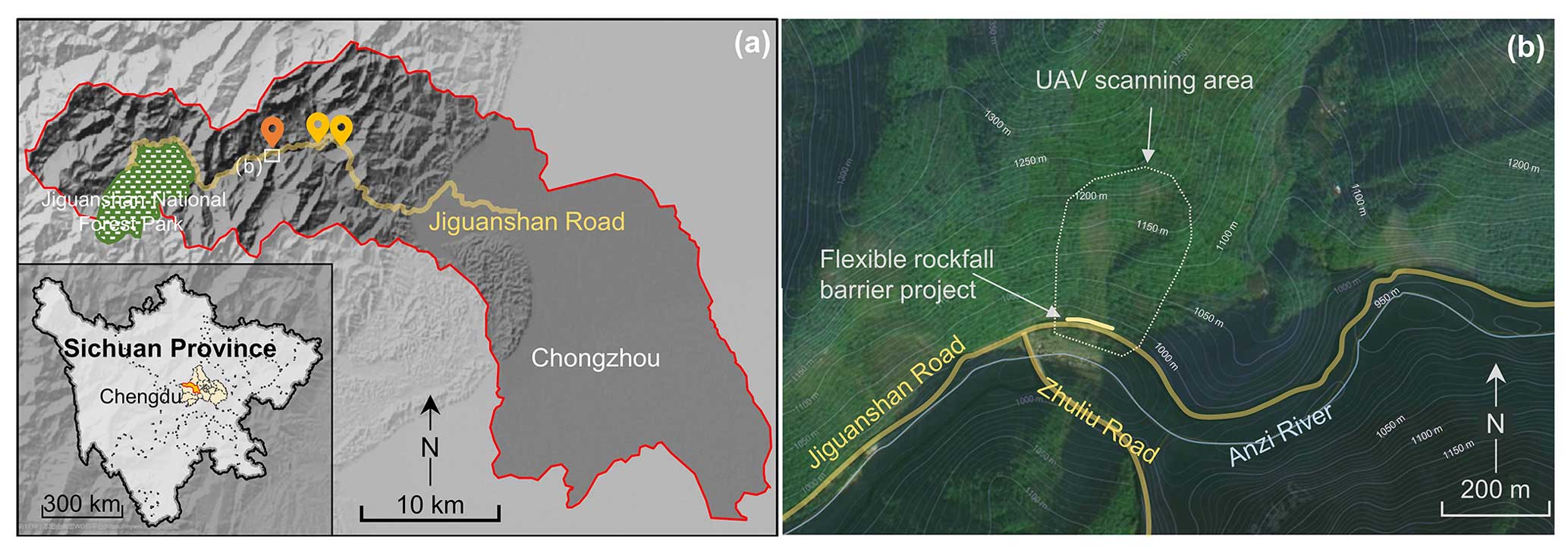
Figure 1Geological map of the rockfall disasters: (a) regional terrain and the location of the three disaster sites. Map data: https://datav.aliyun.com/portal/school/atlas/area_selector (last access: 27 July 2023). (b) Regional aerial image of the case presented in this paper. Image: https://www.tianditu.gov.cn/ (last access: 27 July 2023).
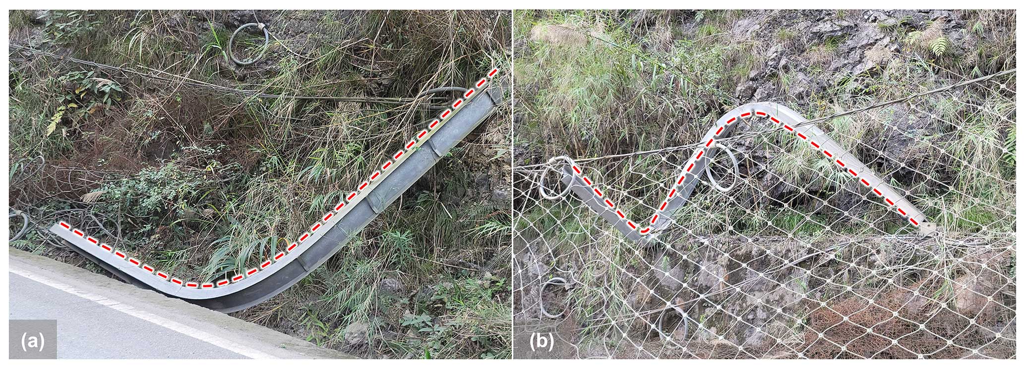
Figure 2Steel column buckling forms of the other two flexible rockfall barrier projects: (a) “C”-shaped compression buckling and (b) “S”-shaped bending and torsion buckling.
UAV aerial photography and measuring tools make up most of the survey methods. The DJI Mavic 2pro drone, whose precision is 2000 pixels, was used to capture aerial photography. A 1 mm standard scale tape measure and a 0.1 mm standard Vernier scale were used for measuring.
Based on the slope inclination photography obtained by UAV, a 3D digital model of the terrain was constructed using ContextCapture software (Bentley, 2021), with a reduction accuracy of centimetre level. The 3D model of the scanned slope is depicted in Fig. 3a; it is roughly 276 m high and at an angle of 45°, with a steep top and a gentle bottom. The hill was primarily covered by medium-high shrubs and bushes. Its foot was predominantly covered by plants including ferns, bamboo, and reed-like herbs, typical in southern and southwestern China. Sedimentary rock formations were exposed in the concave cavity that divided the rock into broken blocks or pieces of various sizes. The area on the slope where new rock layers were exposed after rock spalling was presumed to be the source of rockfalls. The rockfall source was located 105 m above the stopping point at the bottom of the hill and was 22 m lateral along the road. A small amount of gravel and debris was scattered in the gully, and the vegetation along the front section of the gully was severely destroyed. The gully, about 2 m wide, had a minor quantity of rubble and garbage spread throughout it, and the vegetation along the front half of the gully had been severely devastated (Fig. 3). Rockfalls had been stopped by the retaining walls and the flexible rockfall barrier built at the foot of the slope.
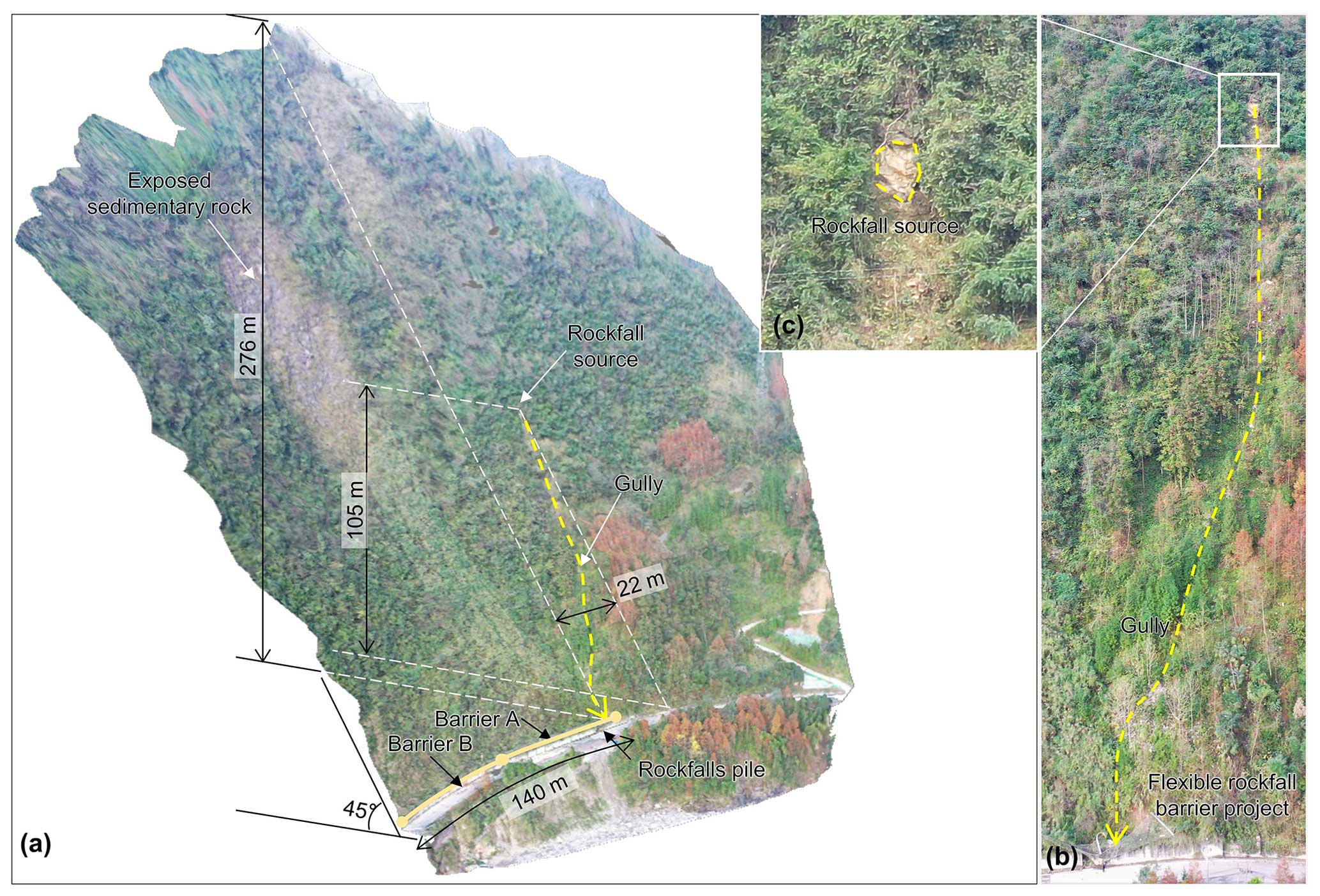
Figure 3Investigation results of the rockfall source area and trajectory. (a) The digital model of the slope; (b) rockfall impact gully; (c) rockfall source.
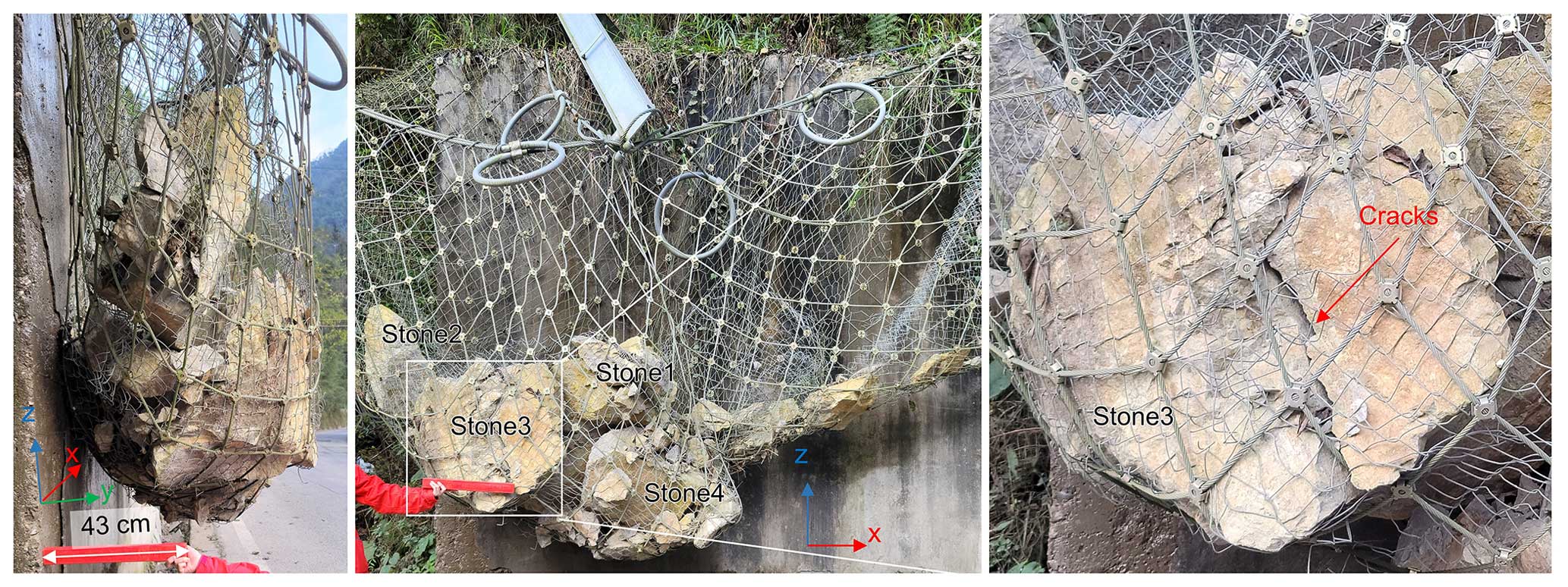
Many intercepted rockfalls, mostly tuff and muddy, were pocketed inside the nets of the protection system, as depicted in Fig. 4, with sharp angles and disparate blocks. The four largest blocks of these stones could be approximated as four cubes: Stone 1 was 0.5 m × 0.5 m × 0.5 m, Stone 2 was 0.3 m × 0.3 m × 0.7 m, Stone 3 was 0.8 m × 0.9 m × 0.7 m and Stone 4 was 0.4 m × 0.4 m × 0.4 m. Stone 3 with cracks was thought to have been broken after hitting the barrier, while the other stones seem to be have been crushed in the movement. The diameter of the remaining debris was about 0.05–0.1 m.
2.2 Description of the protection project
Two flexible rockfall barriers, Barrier A and Barrier B, have a total length of roughly 140 linear metres and are 70 linear metres long (Fig. 3a). They were situated above the retaining wall at the base of the slope mentioned in Sect. 2.1. Barrier A, impacted by rockfalls, was the subject of a thorough investigation in this research (Fig. 5a). Eight support posts divided Barrier A into seven spans, each 10 m wide. Two of the seven spans, S1 and S2, were damaged by rockfalls and collapsed. The eight 5 m high steel columns served as the support posts, numbered P1–P8, and were bolted to the base with a specific swing space in both the longitudinal and transverse directions (Fig. 5b and 4e). Bolted to the top of the retaining wall were the bases. To guarantee the stability of the steel columns, the upper anchor ropes, border anchor ropes, and guy ropes were snapped to their top (Fig. 5c). The ends of steel columns P1 and P8 were fixed with support ropes (including upper, lower, and border support ropes) by rope buckles (Fig. 5e), the upper support rope of the middle spans was lapped to the top of the support posts (Fig. 5c), and the lower support rope of the middle spans passed through the rings on the column bases (Fig. 5d). As energy-consuming devices, brake rings were connected to the upper anchor rope and to the upper and lower support cables near each column end (Figs. 5b and 4c). A steel wire rope net and steel wire mesh net made up the interception unit (Fig. 5c). The steel wire mesh net was connected to the steel wire rope net and support ropes by steel wire. The steel wire rope net was woven by winding ropes to the support ropes, and was hooked to the end of the column. All the anti-rust and corrosion plating of the steel remained intact, with no signs of rust or corrosion. The design protection energy of this project is determined to be 250 kJ based on the specifications of the major components presented in Table 1, which are consistent with the general specifications of a specific flexible rockfall barrier with a protection energy of 250 kJ described in China's former industry norm “JT/T 528-2004, Component of flexible system for protecting highway slope” (JT/T 528-2004, 2004).
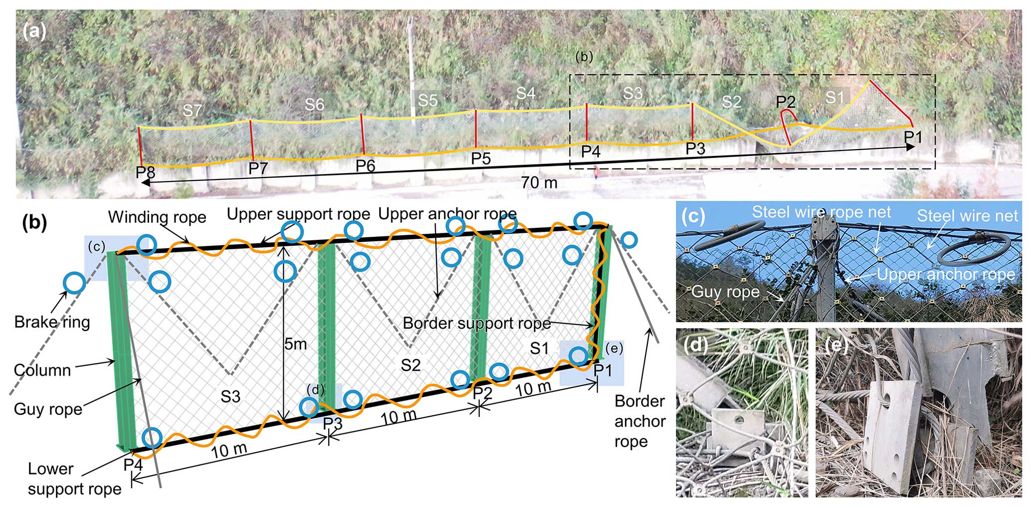
Figure 5Structure composition of the flexible barrier. (a) Overall photo of the project; (b) relationship of component connections; (c) details of column head; (d) failure of column base at the mid-span; (e) failure of border column base.
Table 1Component specifications of the flexible rockfall barrier project.
* The content of this table adopts the coding structure required by JT/T 1328-2020 (2020).
2.3 Damage phenomenon of the flexible rockfall barrier
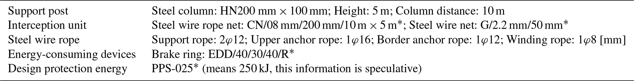
The flexible rockfall barrier intercepted most of the blocks, but the protection project could not keep offering protection since multiple components broke. The main damage phenomena include:
-
The steel column was buckled and destabilized. Due to extreme buckling instability, column P2 could not withstand further pressure (Figs. 6a and 5b).
-
The column base was dislodged. The base of steel column P2 detached from the column base on top of the concrete retaining wall (Fig. 6a).
-
The rope anchoring point failed. Due to the anchoring end falling off, the upper anchor ropes connecting steel columns P1 and P2 were not properly functioning (Fig. 6a).
-
The steel column was falling off. Due to the footing breakdown of steel column P1 and the border anchor rope falling off from the column end, steel column P1 ultimately toppled. Coupled with the instability of steel column P2 and the upper anchor rope breaking off, the interception spans S1 and S2 overturned (Fig. 6a).
-
Energy consumption of the brake ring was insufficient. None of the brake rings deployed on this flexible rockfall barrier showed any discernible activity. The brake rings were blocked at the end of the column because they were set on the support ropes in the middle spans. It was almost impossible for the support ropes to slide (Fig. 6c). The brake rings on the support ropes were directly prevented from being activated by the steel wire rope net and the winding rope since the support ropes were connected to the net by the winding rope (Fig. 6d).
The impact energy of rockfalls on the system was estimated to have a low value because the brake rings lacked an evident working phenomenon, the wire ropes connected to the brake rings were not broken, and the steel wire rope net was intact.
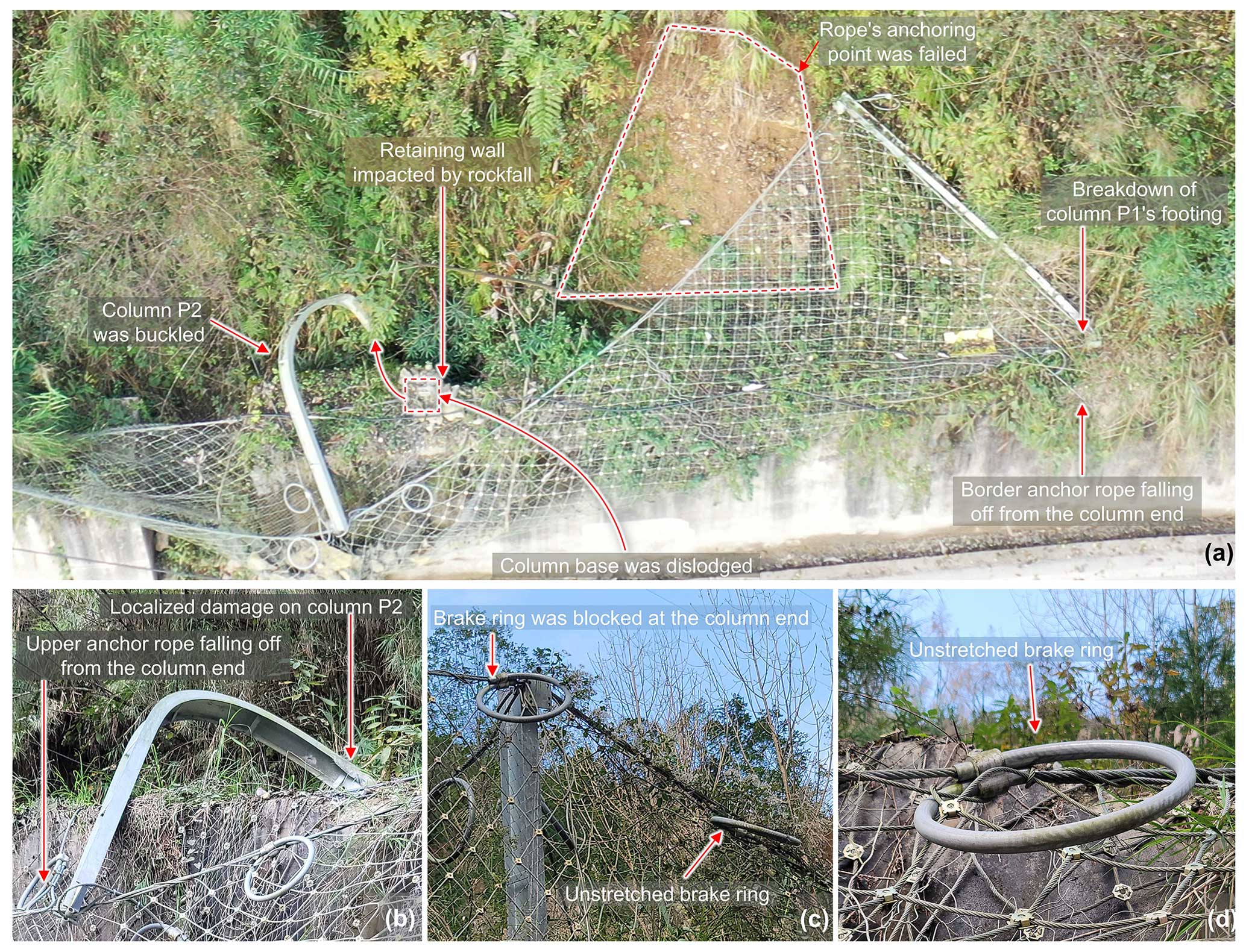
Figure 6Damage phenomena of the flexible barrier. (a) The damaged two-span structure; (b) failure of column P2; (c) non-working brake rings on both sides of column P3 end; (d) connection relationship between the brake ring and the support rope and the steel wire rope net.
Numerical simulation was used to recreate the process of rockfall rolling and impacting the mitigation measure at the investigation site in order to gain insight into the dynamics and the causes of damage to the protection project (Yuen et al., 2023).
3.1 Initial state of the rockfall impact on the flexible barrier
The main factors for this back analysis are the impact kinetic energy and impact position of the rocks in contact with the flexible barrier. Using the Rocscience RocFall2 software, which employs a probabilistic statistical method that integrates slope shape, coefficient of normal restitution (Rn), coefficient of tangential restitution (Rt), friction angle, and roughness, the movement process of the rockfall was used to determine the impact energy (Rocscience, 2023; Sun et al., 2019). The slope where the gully was located described in this paper was primarily covered by shrubs, as shown in Fig. 3b, similar to the surface of the slope of an engineering site in Songpan, southwest China, described by Hu et al. (2018). Therefore, the slope characteristic parameters employed in this study refer to Hu et al. (2018), and they also fit within the range of the parameters that have been given by Hu (1989) for this kind of slope condition (Table 2). The rockfall initial condition parameters of the Rocscience RocFall analysis were an initial velocity of 0 m s−1, a volume of 0.9 m3, and a 2500 kg m−3 density. The crushing of rocks was not considered in this calculation procedure, and the size and source of the stones were constant. The number of rocks thrown was 10 000 in this simulation.
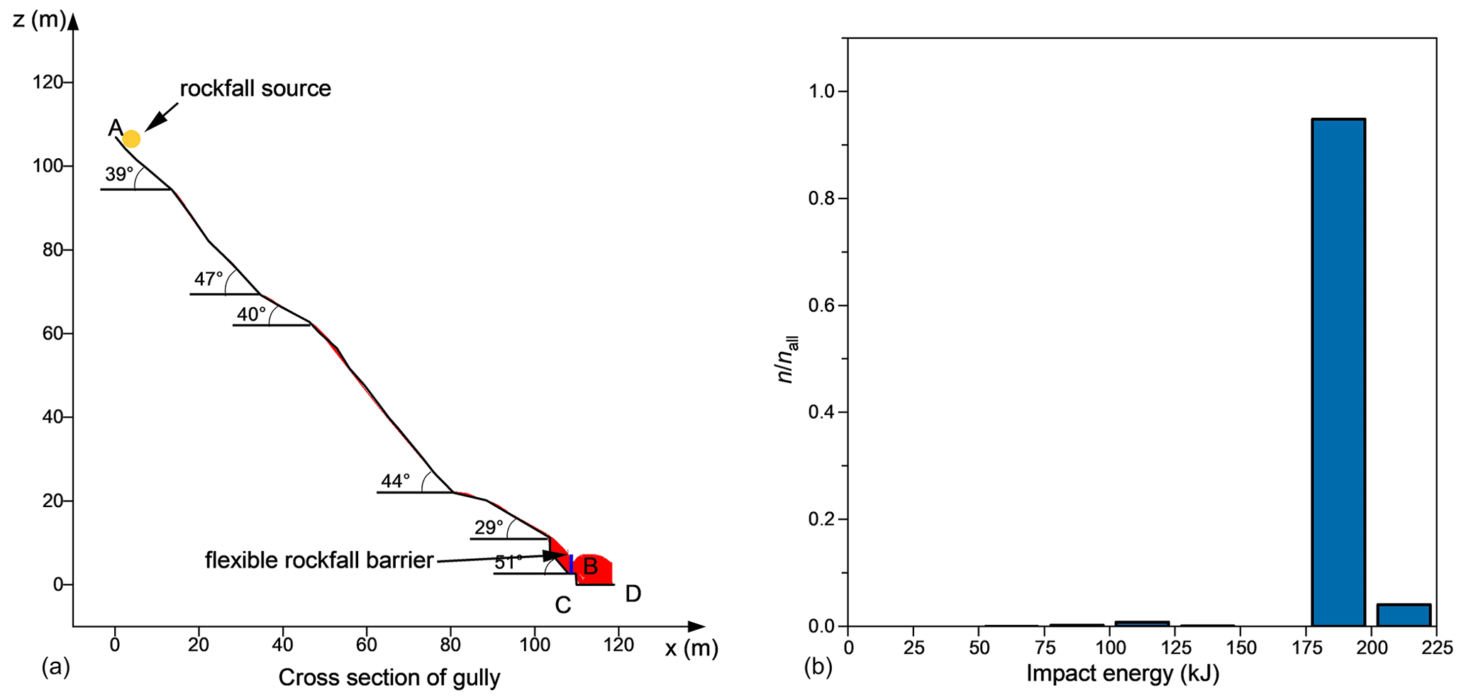
Figure 7Rock mobility analysis: (a) trajectory of rockfall and (b) probability distribution of kinetic energy of falling rocks at the flexible barrier.
The number of rockfalls that reached the net (nall) after 10 000 calculations was 3433. Figure 7b depicts the distribution of the kinetic energy of rockfalls that impact the flexible barrier. The impact energy ranges from 73.64 to 220.6 kJ, with a maximum value lower than the project's design protection energy level. The final determination of the impact energy of the stone impacted on the system was 100 kJ in the FE simulation (Sect. 3.2); under seven trial calculations the impact energy was 75, 100, 125, 150, 175, 200, and 225 kJ. This settled energy is outside the range analysed to be the most likely, 175–200 kJ, and thus the cause is speculated to be that Rocscience RocFall primarily reflects the macroscopic scenario of rockfall movement on the slope, but depicts less regarding the specifics of the rockfall movement process. Figure 6a indicates that rockfall hit the retaining wall before hitting the flexible barrier; this impact probably reduced considerably the energy of rockfall hitting the flexible barrier.
The lower right-side section of the lower flange of P2 steel column exhibited symptoms of localized damage, which leads us to believe that this was where the collision occurred (Figs. 6a and 8a). The initial velocity of Stone 1 in Sect. 3.2 was set to 0.5, −5, and 5.5 m s−1 to ensure it harms the net after hitting the steel column flange in P2. For Stones 2, 3, and 4, uniform initial velocities of −4.8, −7, and 4.8 m s−1 were defined, respectively (the velocities listed above are the x-, y-, and z-axis sub-velocities, shown in Fig. 10).
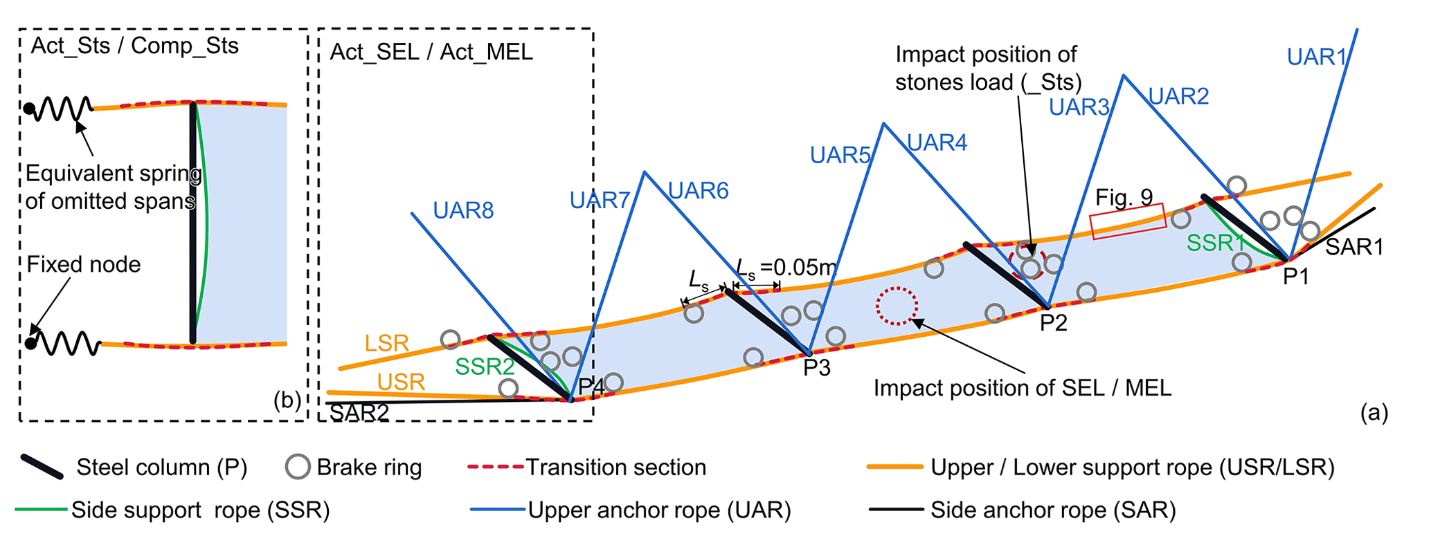
Figure 8Structure representation of the actual model (Act_) and the comparative analysis model (Comp_). (a) Act_SEL and Act_MEL. (b) Act_Sts and Comp_Sts.
3.2 Construction of the FE model
The back analysis of the rockfall impact on the flexible rockfall barrier was carried out using the FE method program ANSYS_2021_R1_LS-DYNA_mpp_r13 (LSTC, 2021). The simulation method is detailed in the literature (Yu et al., 2021, 2018b). The model components were all constructed of nonlinear materials, and the component specifications of the computational model were similar to those of the project. Key adopted parameters are summarized in Table 3. This simulation model is marked as Act_Sts.
Table 3Summary of parameters used in the numerical simulations.
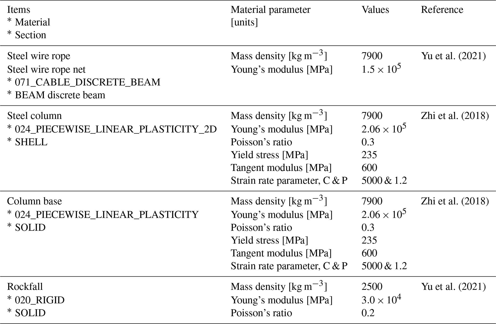
Considering this paper focuses on the damage mechanism of the system and the decay law of impact action between spans (Qi et al., 2014), and in order to minimize the use of computational resources, the FE model Act_Sts was only established for spans S1, S2, and S3. Support ropes and brake rings were installed on the outside of steel column P3 to ensure a realistic dynamic response on this column (Fig. 8a). The steel column and base material were set with a failure plastic strain of 0.185. The axial force controls the breaking of the wire rope, and thus the breaking strength of the wire rope with diameters 8, 12, and 16 mm is set to 49.4, 111, and 198 kN, respectively. The steel wire mesh net was not included in the simulation model because it was employed in the project as a member to stop the fine debris and has no noticeable force effect.
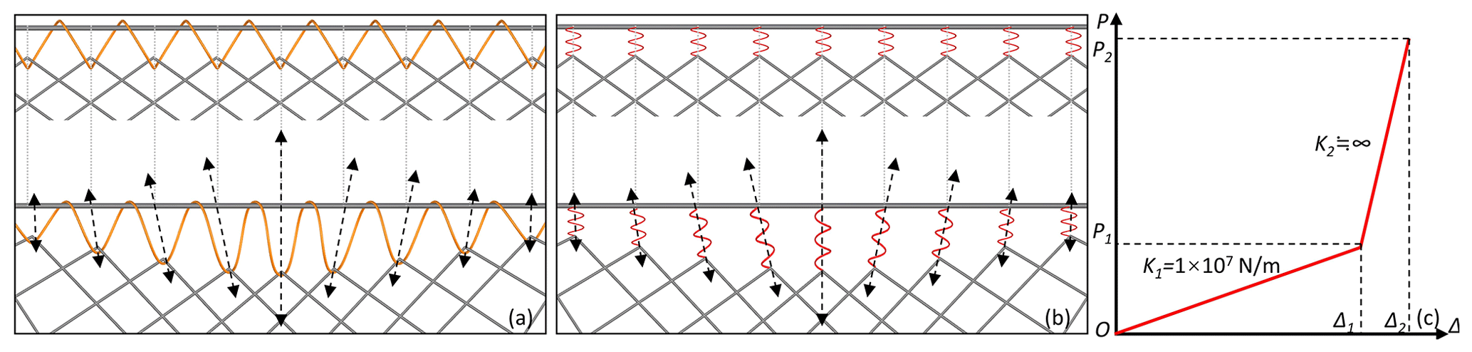
Figure 9Spring equivalent model for winding rope. (a) Before and after winding rope deformation. (b) Before and after spring equal model deformation. (c) Bilinear constitutive model of the winding rope spring.
Compared to the standard numerical model of flexible rockfall barrier, the following special treatment was applied to reveal the actual failure state of the project:
-
The column end had a wire rope net attached to it, which caused a small space for the wire rope to slide along. According to multiple trial calculations, the structural deformation was adequate for the best results when the slide amount was set at 0.05 m.
-
The winding rope that connects the wire rope net to the support rope is relaxed while the barrier is not in service. However, once the system is impacted, the winding rope of the affected part will elongate, causing the gap between the net and the support rope to expand (Fig. 9a). As a result, extension spring units, which were applied to the connecting unit between the support rope and the flexible net, were used as equivalent to the winding rope (Fig. 9b). The ends of the winding rope spring were fixed. Its constitutive model was bilinear, where k1 was 1×10⁷ N m−1, Δ1 was 0.1 m, and k2 was infinite in the model Act_Sts (Fig. 9c).
-
Due to the phenomena of column foot failure in the actual project (see Sect. 2.3), the Act_Sts model plastic strain of failure was defined for the materials at the weld of the base connection plates of columns P1 and P2, with values of 0.0065 and 0.007, respectively, after trial calculation.
-
After trial calculations, it was determined that ropes UAR4 and SAR1 would fail at 0.14 and 0.88 s after the rockfall contact with the net, respectively.
-
Because the UAR2 and UAR3 anchorage points may break before or after impact, a failure tension value of 44.9 kN was determined after two trial calculations with zero and more than zero failure tension values.
A comparative model (Comp_Sts), where the connection damage in Act_Sts was corrected, and the same impact condition calculation as in Act_Sts, was carried out to determine the primary source of the damage to this protection structure. The specific corrective measures are as follows: (1) the anchoring force of the rope's anchorage point was increased to 396.24 kN, two times the breaking force of an upper anchor rope with a diameter of 16 mm. (2) The plastic strain of failure of the materials at the weld of base connection plates was raised to 0.185. (3) Reinforcing the connection node of column P1 to rope SAR1 and the connection node of rope UAR4 to column P2 by setting a failure axial force on the wire rope rather than time control in Act_Sts.
3.3 Simulation results
3.3.1 Protection process
The process of rockfall impacting the flexible rockfall barrier is depicted in Fig. 10 as calculated by Act_Sts, restoring critical phenomena such as anchor rope shedding, rope anchorage point failure, and the base connection plates of column failure. Finally, the entire protection system was destroyed, and the rockfalls were piled up to the right of the S1 and S2 nets near the end of column P2, essentially in the same state as the actual project.
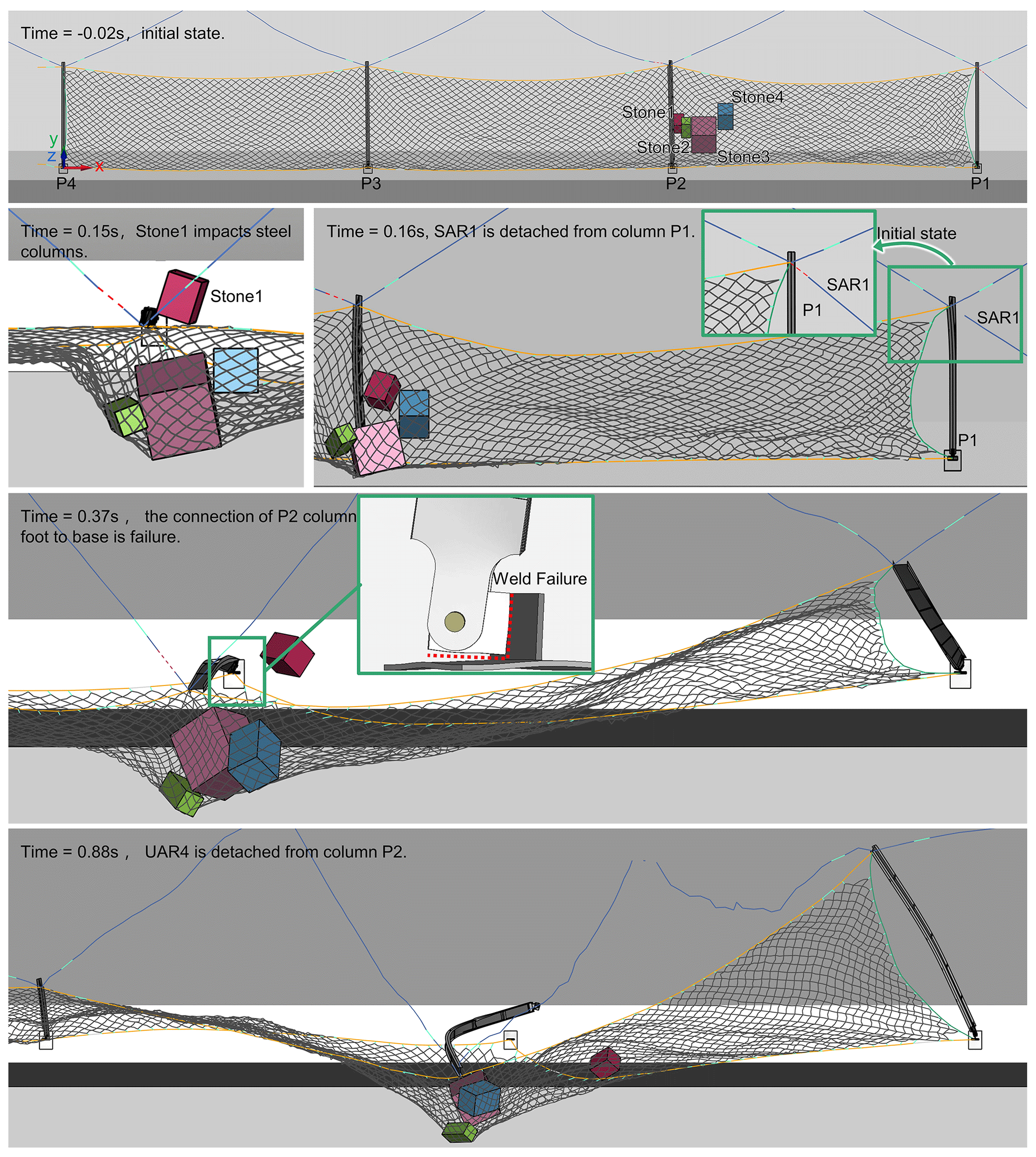
Figure 10Key frames of the impact process (the 0 instant occurs when Stone 3 touches the wire rope net).
3.3.2 Component damage
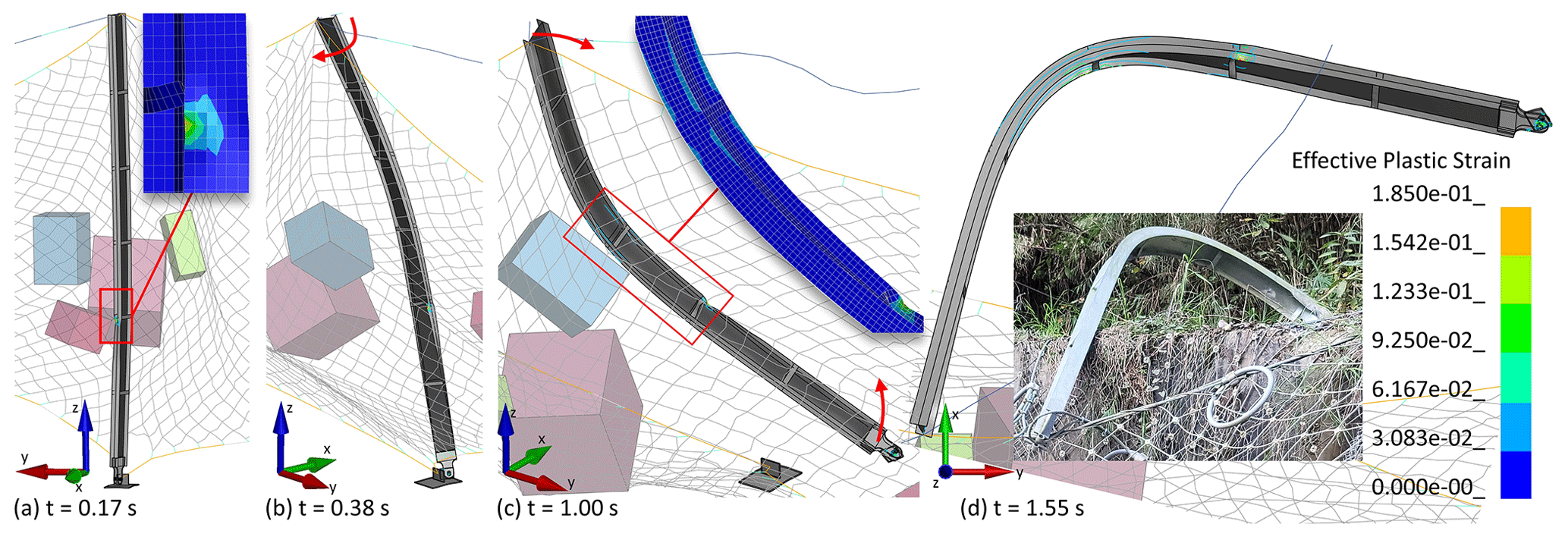
As in the actual project, steel column P2 suffered substantial buckling damage, and the flange also sustained localized damage. The foot damage to border column P1 caused the column to be dumped entirely. Figure 11 depicts the buckling progression of steel column P2 in Act_Sts: at 0.15 s, Stone 1 impacted steel column P2, causing localized damage at the impact point; at 0.25 s, the stress on both sides of the end of the steel column P2 was out of balance after the failure of the anchorage point connected to the ropes UAR2 and UAR3, while the column foot was restrained and column P2 was twisted; at 0.37 s, the base connection plate of the column P2 weld failed as a result of the column foot twisting, releasing column P2 from the torsional restraint and turning it into a compression-bending member; at 0.98 s, column P2 was impacted by the rebounding stone; finally, a C-shaped buckling state was created by constantly compressing and stressing steel column P2.
The numerical simulation reproduced the phenomena of rope failure, such as the failure of the rope anchorage point connected to upper anchor ropes UAR2 and UAR3 and the disengagement of the side anchor rope SAR1 and upper anchor rope UAR4 from the end of column P1. Figure 12 shows the temporal evolution of the wire rope internal force, where axial force extreme of all the wire ropes is below the breaking strength of the corresponding specification wire rope. However, considerable tension pulses were seen in LSR and UAR3 because of the confined member slide deformation. Additionally, each wire rope in the wire rope net had an axial force that was consistently less than the breaking force.
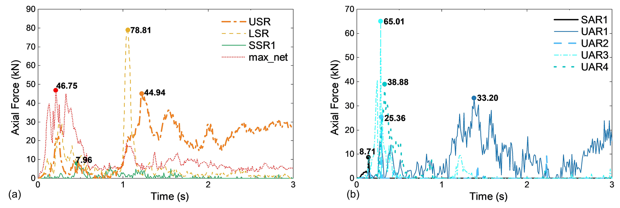
The simulation result shows that the brake ring connected to the lower support rope near column P1 stretched up to 0.35 m because the model Act_did not limit this elongation. However, in the actual project, the brake ring would be constrained by the wire rope net winding rope and could only stretch up to 0.20 m. There was limited elongation (elongation ≤ 0.02 m) in the other brake rings. Generally, the Act_Sts overall impact process and component reaction results aligned with the engineering site's actual situation.
3.3.3 Energy evolution of the protection process
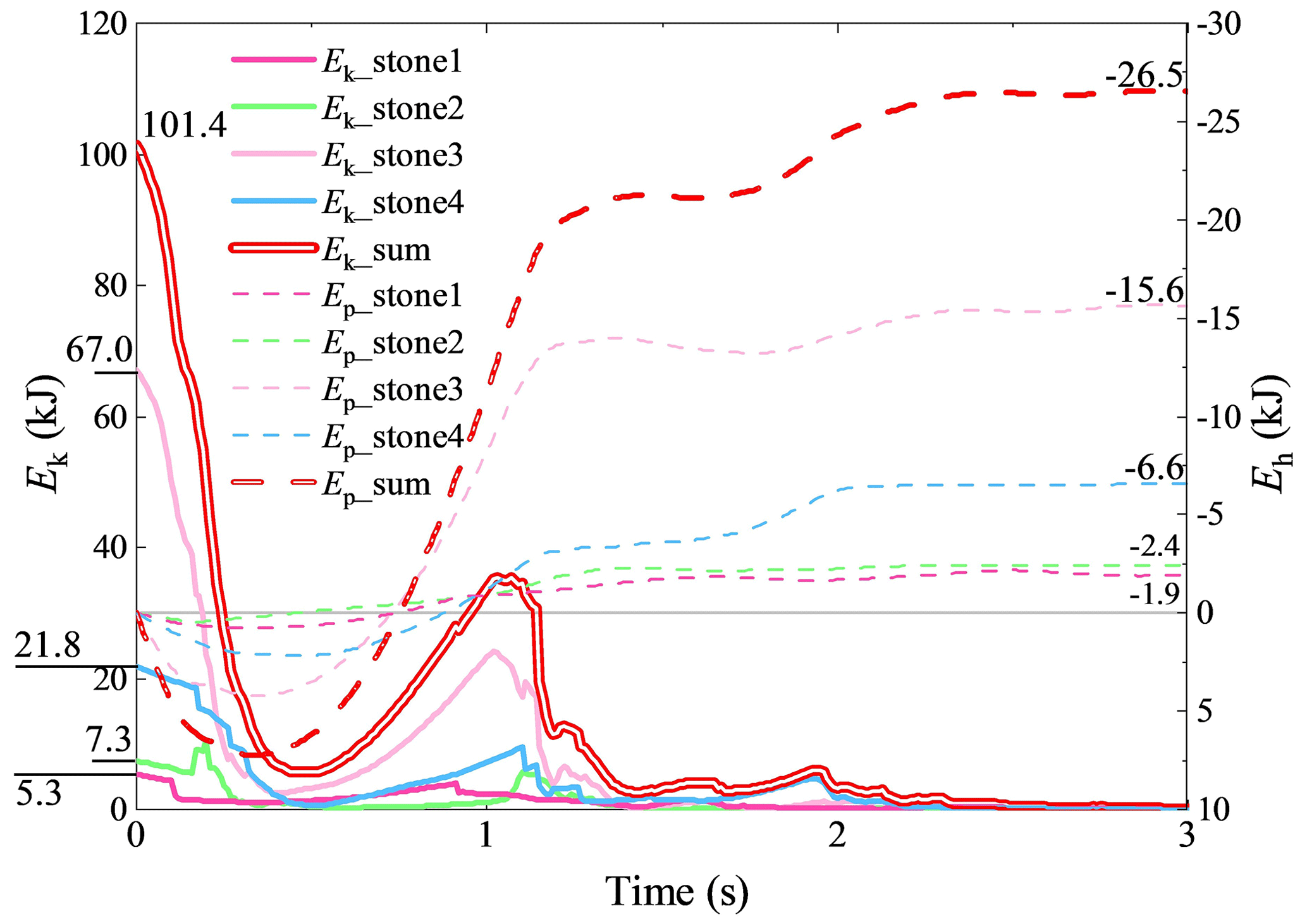
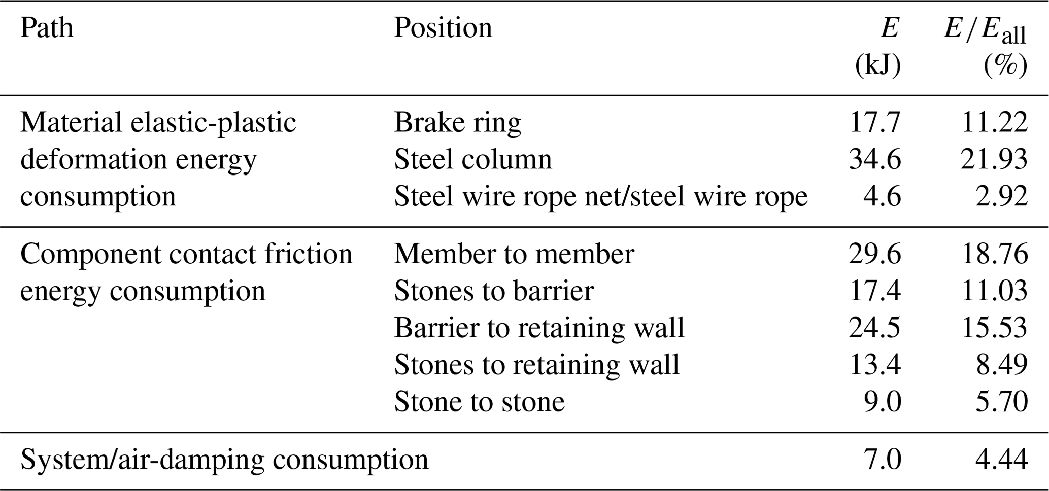
An energy analysis of the protection process was carried out based on the simulation results to assess the contribution of the protection system to the interception of rockfalls. The initial moment of impact kinetic energy and potential energy of the stones was taken from the moment when the first rock, Stone 3, touched the barrier. The temporal evolution of kinetic energy and potential energy of rockfalls shows that the total impact kinetic energy was 101.4 kJ, which is 40.1 % of the design protection energy of the flexible rockfall barrier (Fig. 13). During the protection process, the gravitational potential energy of rockfalls and flexible barrier decreased by 26.5 and 29.9 kJ, respectively. Therefore, the energy consumed in the protection process (Eall) was 157.8 kJ. Table 4 displays the energy distribution during the protection process: the three pathways of energy consumption are material elastic-plastic deformation energy consumption, component contact friction energy consumption (including winding rope energy consumption), and system/air damping consumption, with energy consumption of 56.9, 93.9, and 7.0 kJ, accounting for 36.06 %, 59.51 %, and 4.44 % of the total energy consumption, respectively. It is noteworthy that the steel column consumes 34.7 kJ, about 60.83 % of the energy consumed by material elastic-plastic deformation.
3.3.4 Structural damage mechanism
Combining the information from the field investigation and the back analysis, the reasons for the failure of the flexible rockfall barrier are analysed as follows:
-
Incorrect installation of the flexible net: the wire rope net and the support rope were connected by winding rope; as a result, when the barrier got impacted, the winding rope tightened, and the wire rope net could not fully move along the support rope. The steel column then instantaneously entered the pressure-bending state due to the wire rope net being hooked on the end of the column, which directed the impact force acting on the net to the end of the column.
-
Insufficient buffer space for the support rope to the columns: since the support ropes were fixed to the border column ends, lateral tension would cause the border columns to tilt sideways when the barrier was impacted.
-
Incorrect placement of the brake ring: the brake ring, which should be the component with the highest percentage of energy consumption, only dissipated 17.7 kJ impact energy, approximately 11.2 % of the total energy consumed. This is because the brake ring cannot be fully stretched due to the intertwining of the support rope, winding rope, wire rope net, and brake rings.
-
System cannot achieve large deformation: the system deformability was also constrained because the net and support ropes were limited to slide. As a result, the “large deformation” characteristic of flexible barriers was not mirrored in the system, and the impact energy could not be completely dissipated. Additionally, due to the limited deformation development of the system, which resulted in a small y-directional pull force transferred from the column end to the upper anchor rope, the brake ring connected to the upper anchor rope could not be fully stretched to release the impact force.
-
Insufficient wire rope anchorage point: the anchorage points of the upper anchor ropes UAR2 and UAR3 collapsed after the impact due to insufficient anchorage force. Hence UAR2 and UAR3 were unable to stabilize the steel column.
-
Inadequate steel column restraint: besides the upper anchor ropes failing as described in (5), the corresponding steel columns lost the essential bond as ropes SAR1 and UAR4 fell off from the column ends. Additionally, steel columns P1 and P2 did not work because the weld failed on the column bases.
Model Comp_Sts strengthens the connections as well as the wire rope anchorage points. The result of Comp_Sts shows that column P1 was always in the normal working condition, column P2 did not enter the torsional force state, but column P2 still entered the C-shaped compression bending flexure state as in the Act_Sts working condition. Moreover, no damage to the members due to low material configuration was found in the field survey results, in model Act_Sts or in model Comp_Sts. This means that the three incorrect connections – inadequate flexible net installation, insufficient buffer space for the support rope to the columns, and inadequate placement of the brake ring – are the primary causes of the inability of this mitigation project to withstand the rockfall impact. Due to the incorrect component connection form, a sliding system could not be formed, and the buffering mechanism of the flexible rockfall barrier also could not be developed. This resulted in an impulse force at the column end, which eventually caused the steel column to buckle and the system to collapse. Therefore, achieving substantial system deformation requires adequate relative sliding motion between the components, especially the sliding ability of the support rope at the column end (Fig. 14).
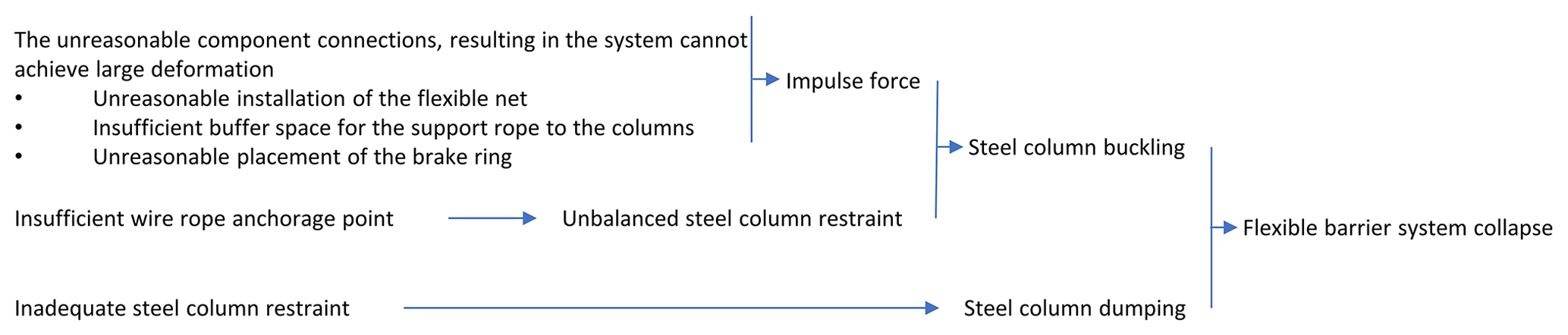
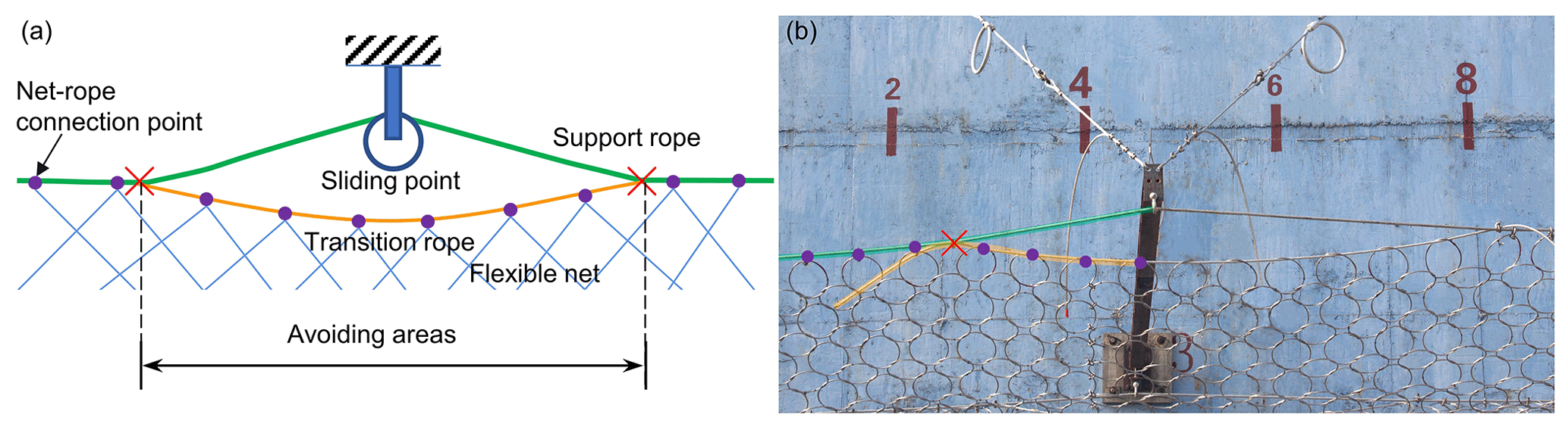
Figure 15The transition rope applied between column ends and support ropes: (a) structure schematic and (b) project photograph.
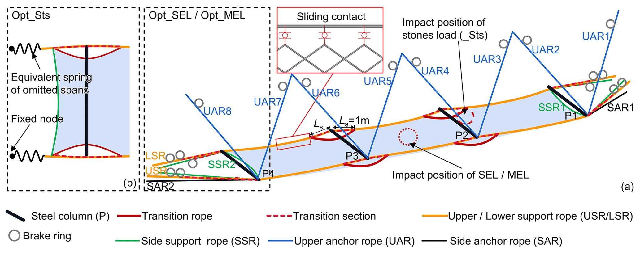
Figure 16Structure representation of the model Opt_. (a) Simulation models Opt_ SEL and Opt_MEL. (b) Simulation model Opt_Sts.
4.1 Optimization measures
Whether the support rope enables sliding at the end of the steel column depends on the connection mechanism employed between the steel column end, the support rope, and the flexible net. The transition rope should be used in most cases where the design protective energy is 1000 kJ or less and the support rope does not slide a significant distance along the end of the column (Yu et al., 2018b). The transition rope can prevent the lateral force at the column end and the sharp rise in the axial force of the steel column generated by the net jamming, both of which cause the column to buckle (Fig. 15).
The control model (Comp_) is optimized based on the analysis in Sect. 3.4, while leaving the specifications of the system components unaltered, and the optimized model is denoted as Opt_ (Fig. 16). The optimization measures are: (1) removing the brake rings from the flexible net connection portion and replacing them with a single brake ring attached to the support rope and all brake rings positioned at the anchor end of the wire rope; (2) changing the connection between the column end and the support rope to a transition rope whose length of the transition section Ls is set to 1 m, the maximum elongation of the linked brake ring; (3) extending the support rope from the end of the border column to the slope, and the support rope is in sliding relationship with the border column end; (4) using shackles to link the support ropes to the net or threading the support ropes through the net holes to ensure the relative sliding properties between the net and the support ropes; (5) setting an initial x-axis angle of 10° for the barrier to reduce the chance of it being reverse-tipped after impact.
Six impact conditions were calculated for the actual model (Act_) and the optimized model (Opt_) of the four stones back-analysis load (_Sts), service energy level load (_SEL), and maximum energy level load (_MEL), in addition to the condition calculated as described in Sect. 3. According to JT/T 1328-2020 (2020) and EAD 340059-00-0106 (2023), the impactor of SEL and MEL is a single 26-sided block with an impact velocity of 25 m s−1, the impact site is the midpoint of the midspan, the MEL impact energy is 250 kJ, and the SEL impact energy is 85 kJ.
4.2 Results and discussions
4.2.1 Overall protection up to standard
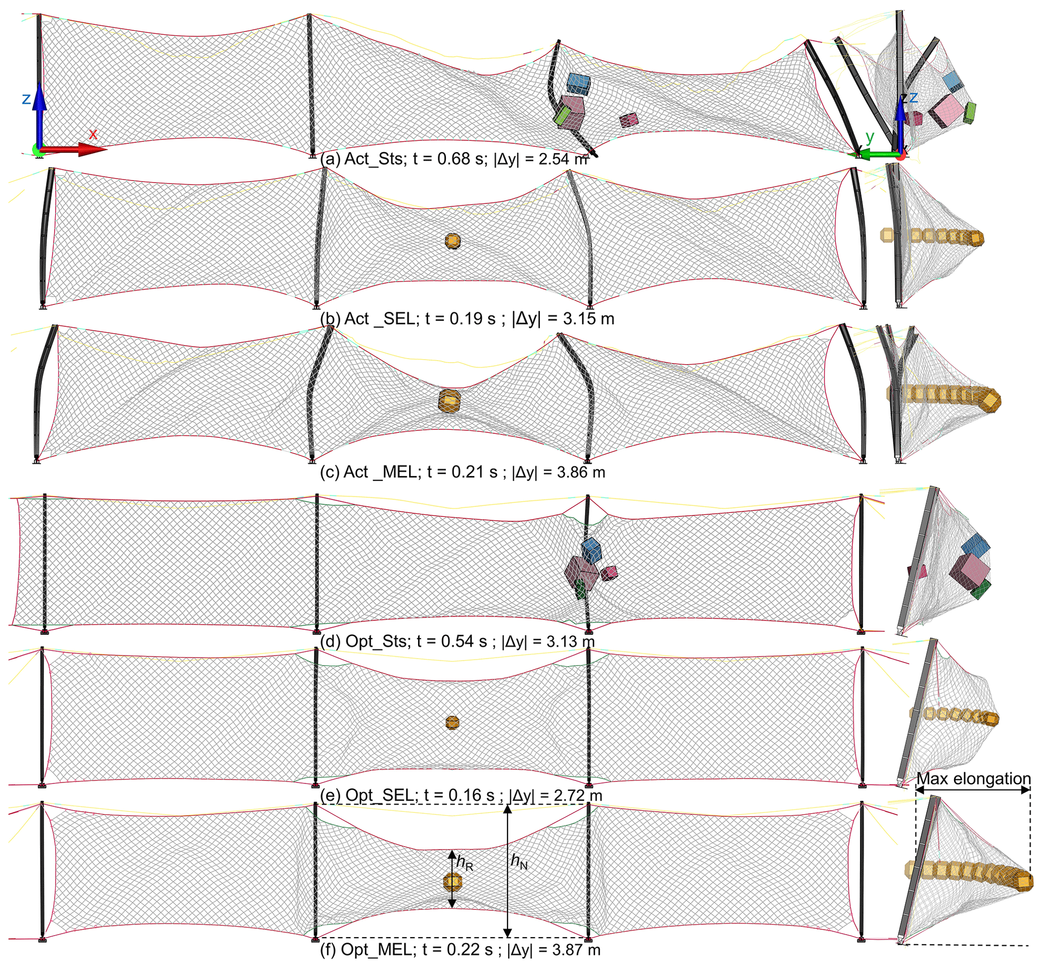
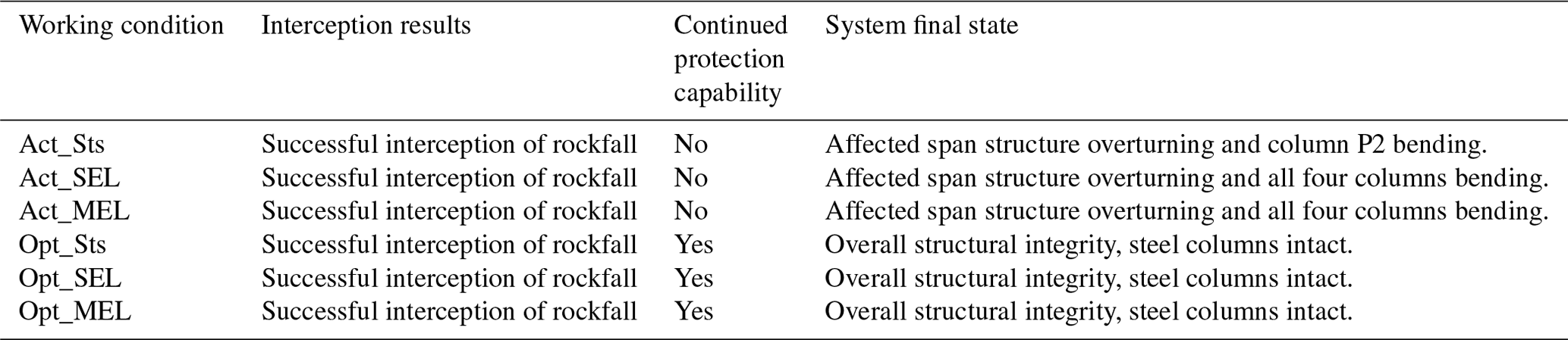
Figure 17 and Table 5 display the outcomes and structure states of the six working conditions. The rockfalls were stopped in all simulation conditions. Still, the model Act_ showed buckling of the steel columns in all impact conditions, significantly weakening the ability of the protection system to continue protecting. If this model had been used for the project, it would have required component replacement and structural repairs before it could continue for protection employment. In the three impact conditions of model Opt_, the entire system maintained structural integrity following impact with no buckling column.
In Opt_SEL and Opt_MEL, the barrier successfully intercepted rockfalls, and the barriers were not broken. After completing the interception, the structure of Opt_MEL is described: as shown in Fig. 17f, the maximum elongation Lmax is 3.35 m (the guidelines require Lmax to be less than 5 m), and the residual height of the net hR is 2.85 m (the guidelines require hR to be larger than 50 % of the nominal height of the kit hN), which means hR needs to be larger than 2.5 m. Therefore, the model Opt_ complies with standards for class A flexible rockfall barriers with 250 kJ of energy in JT/T 1328-2020 and EAD 340059-00-0106.
4.2.2 Reduction of structural stress
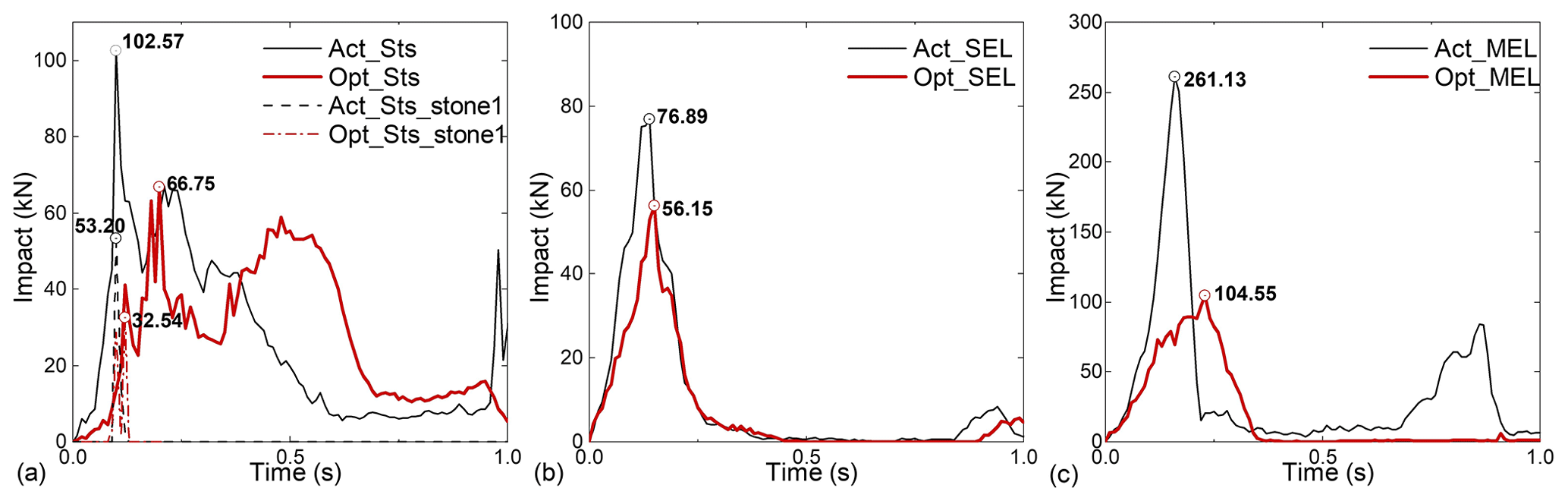
Compared to the model Act_, the impact force between the rockfalls and the barrier decreased dramatically due to the enhanced sliding ability of the components and the improved deformability of the system, which reduced total system stiffness. According to Fig. 18, when model Opt_ is compared with model Act_, the peak impact force drops by 35 %, 27 %, and 60 %, respectively, under the three computational circumstances of _Sts, _SEL, and _MEL. It is clear that the protection concept of the flexible protection system “roll with the punches” can be realized effectively and achieve the design protection energy level of the barrier by altering the connection relationships of the column end to the supporting rope and of the flexible net to the wire rope and the brake ring arrangement position while maintaining the component specifications as-is.
Stone 1 impacted steel column P2 in Opt_Sts just as it did in the Act_Sts case. Still, due to the different system stiffness, the impact force was almost 39 % lower in Opt_Sts than it was in Act_Sts (Fig. 18a). Although the Opt_Sts steel column P2 suffered numerous impacts, none of them seriously damaged it (Fig. 19a). Steel column P2 experienced overall bending at the moment of the most significant system deformation (Fig. 17g). After the impact passed, the steel column recovered, and the entire structure remained stable (Fig. 19a), eventually preventing the system from overthrowing due to the buckling of the steel columns in Act_Sts (Fig. 19b).
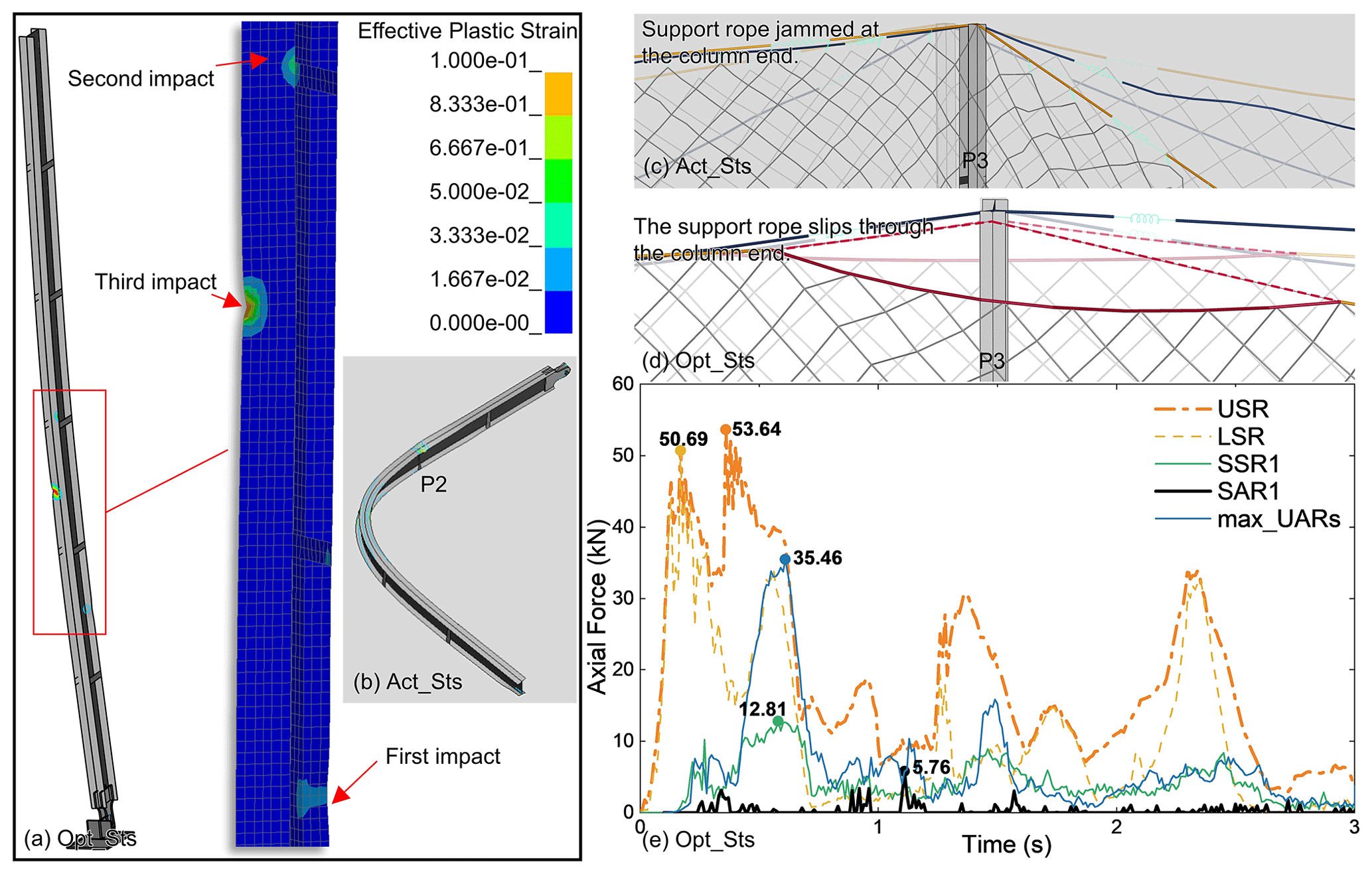
Figure 19Opt_Sts calculation result: (a) column P2 in Opt_Sts has local damage after several hits. (b) Column P2 in Act_Sts is buckling; (c) and (d) are the support rope sliding performance on the end of column P3 in Act_Sts and Opt_Sts, respectively (semi-transparent for pre-impact and saturated colour for post-impact). (e) The internal force of part of the wire ropes in Opt_Sts.
In Opt_Sts, the transition ropes prevented the net from jamming at the column end and lessened the deflection of the column caused by the tugging of the support ropes (Fig. 19c and d). Due to the system deformation capacity being improved, the internal force of the wire rope increased more gradually (Fig. 19e), and the phenomenon of the pulse force of the wire rope as seen in Act_Sts did not occur (Fig. 12).
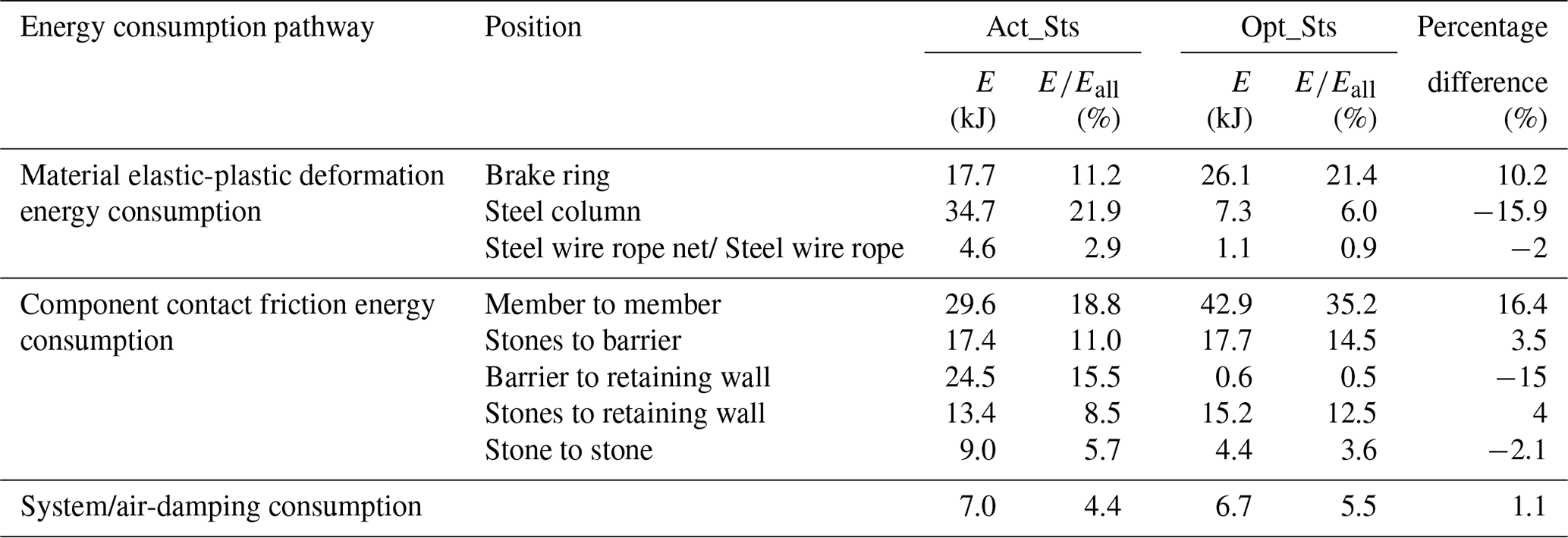
Table 6Energy consumption statistics for Opt_Sts and comparison with Act_Sts.
4.2.3 Optimization of energy consumption pathways
The energy analysis of the Opt_Sts protection process was carried out by the method described in Sect. 3.3. The total impact kinetic energy was 101.4 kJ. During the protection process, the gravitational potential energy of rockfalls and flexible barriers decreased by 28.0 and 7.4 kJ, respectively. Therefore, the actual energy consumed in the protection process of Opt_Sts is 122 kJ. The statistics of energy consumption in Opt_Sts are shown in Table 6. The comparison with the results of Act_Sts shows the following: in Opt_Sts, friction energy dissipation between members replaced elastic-plastic deformation energy dissipation of steel column material as the primary approach for energy dissipation, with an increase in the proportion of this part of energy dissipation from 18.8 % (in Act_Sts) to 35.2 %. Additionally, energy consumed by brake rings, which increased from 11.2 % (in Act_Sts) to 21.4 %, made up the second-largest portion of Opt_Sts. The percentage of energy dissipated by the energy dissipator increased as impact energy increased (it is worth pointing out that the rate of energy consumed by brake rings in Opt_MEL increased to 33.96 % of the total impact kinetic energy consumed in the protection process). In conclusion, after structural optimization, the consumed energy was decreased in “undesirable” pathways such as buckling energy dissipation of steel columns and friction energy dissipation between the system and the retaining wall and increased in “desirable” pathways such as elastic-plastic deformation energy dissipation in energy dissipators and friction energy dissipation in structure components.
The results show that, without changing the specification of the components, only modifying the connection relationship of the components can significantly improve the performance of the flexible barrier, such as the internal force curve of the components tends to be smoothed, the percentage of energy consumption of the brake rings rises, and the stability of the components is enhanced. Therefore, the correct connection relationship of the components is very important during field installation and is a key factor in the full realization of the large deformation of the system. Although there should be consensus on this in the field, this paper is the first to analyse a disaster site by revealing the impact process and quantifying it. This is of non-negligible engineering significance for mountainous regions where flexible barriers are in great demand, such as the Alpine region in Europe, south-central Africa, Central Asia, and the Western North America and Western South America.
Through the field investigation and the numerical back analysis on a typical flexible rockfall barrier project that is impacted by rockfalls, we studied the phenomenon that the actual impact energy to the flexible barrier is significantly lower than the design protection energy. The conclusions are as follows:
-
The system components cannot sufficiently slide between each other, e.g. the support ropes do not have enough slip space at the end of the post, the brake rings are entangled with the flexible net and winding ropes, the flexible net is hooked at the column end, etc., thereby preventing the system from realizing the large deformation of the energy dissipation, and limiting the ability of the brake rings to dissipate energy.
-
Incorrect component connections caused the flexible rockfall barrier to break down despite the actual impact energy of the investigated project being only 40.1 % of its designed protection energy level. The main damage phenomena of the project include the steel column being buckled and destabilized, the column footing being dislodged, the rope anchoring point failing, the steel column falling, and the energy consumption of the brake ring being insufficient.
-
Adding transition ropes, anchoring the support ropes to the slope, changing the position of the brake ring of the support ropes from both sides of the column end to the support rope end, and changing the connection between the net and the support rope to a slidable connection can all effectively prevent the instability of the steel columns without modifying the specification of the system components. The design protection energy and the actual engineering impact condition can both be withstood by the optimized flexible rockfall barrier, and the system structure is unaffected. Compared with Act_Sts, in Opt_Sts, the reduction in total system stiffness leads to a reduction in the peak impact force by 35 %. Furthermore, more impact energy is consumed by “desirable” pathways such as elastic-plastic deformation energy dissipation in energy dissipators and friction energy dissipation in structure components.
In conclusion, the disparity between the project conditions and the test conditions is the primary cause of this flexible barrier's failure in the actual project. For the system to fully utilize the buffering ability of large deformation, the proper assembly relationship is essential while installing it in the field.
The slope topography, rockfall shape, attack angle, system installation morphology, and other field conditions may influence the performance of the flexible rockfall barrier. The influence of these aspects will be further investigated to provide a quantitative analysis based on the qualitative analysis in this research. This analysis will serve as a guide for enhancing the dependability of flexible rockfall barriers.
| _MEL | maximum energy level load |
| _SEL | service energy level load |
| _Sts | 4 stones load |
| Act_ | actual structure in survey case |
| Comp_ | structure of the comparative analysis |
| EDD | energy dissipating device |
| FE | finite element |
| HN | narrow flange H-beam |
| LSR | lower support rope |
| Opt_ | optimized structure |
| P | pillar, steel column |
| PPS | passive protection system |
| S | span, the barrier unit between two columns is |
| one span | |
| SAR | side anchor rope |
| SSR | side support rope |
| UAV | unmanned aerial vehicle |
| USR | upper support rope |
All raw data can be provided by the corresponding authors upon request.
The investigation was conducted by LRL, ZXY, LXL and LP. Data curation was done by QW. The statistical analyses were performed by LRL and LJZ. The original manuscript was written by LRL and ZXY. Supervision and funding acquisition were done by ZXY.
The contact author has declared that none of the authors has any competing interests.
Publisher's note: Copernicus Publications remains neutral with regard to jurisdictional claims made in the text, published maps, institutional affiliations, or any other geographical representation in this paper. While Copernicus Publications makes every effort to include appropriate place names, the final responsibility lies with the authors.
This article is part of the special issue “Natural hazards' impact on natural and built heritage and infrastructure in urban and rural zones”. It is not associated with a conference.
This work has been financially supported by the Sichuan Province Science and Technology Support Program (grant no. 2022YFG0141), the National Key Research and Development Program of China (grant no. 2018YFC1505405), the National Natural Science Foundation of China (grant no. 51678504) and the Key Science and Technology Projects in the Transportation Industry (grant no. 2020-MS3-101).
This research has been supported by the Sichuan Province Science and Technology Support Program (grant no. 2022YFG0141), the National Key Research and Development Program of China (grant no. 2018YFC1505405), the National Natural Science Foundation of China (grant no. 51678504), and the Key Science and Technology Projects in the Transportation Industry (grant no. 2020-MS3-101).
This paper was edited by Maria Bostenaru Dan and reviewed by two anonymous referees.
Bentley: ContextCapture User Guide, chrome-extension: efaidnbmnnnibpcajpcglclefindmkaj, https://docs.bentley.com/LiveContent/web/ContextCapture_User_Guide_EN_PDF-v18/en/ContextCapture User Guide EN.pdf (last access: 21 February 2024), 2021.
EAD 340059-00-0106: Falling rock protection kits, European Organisation for Technical Approvals, http://www.eota.eu/ (last access: 27 July 2023), 2023.
Ferrero, A. M., Segalini, A., and Umili, G.: Experimental tests for the application of an analytical model for flexible debris flow barrier design, Eng. Geol., 185, 33–42, https://doi.org/10.1016/j.enggeo.2014.12.002, 2015.
Gentilini, C., Govoni, L., de Miranda, S., Gottardi, G., and Ubertini, F.: Three-dimensional numerical modelling of falling rock protection barriers, Comput. Geotech., 44, 58–72, https://doi.org/10.1016/j.compgeo.2012.03.011, 2012.
Geobrugg: RXE-10000 barrier product profile, https://www.geobrugg.com/file-78303/downloadcenter/level1-brochures/RXE-barrier/RXE-10000_product_profile_200131-EN.pdf (last access: 27 July 2023), 2027.
Hu, H. T.: Landslides and rockfalls, China Railway Publishing House, Beijing, China, 183 pp., ISBN 9787113004217, 1989.
Hu, J., Li, S. C., Li, L., Shi, S. S., Zhou, Z. Q., Liu, H. L., and He, P.: Field, experimental, and numerical investigation of a rockfall above a tunnel portal in southwestern China, Bull. Eng. Geol. Environ., 77, 1365–1382, https://doi.org/10.1007/s10064-017-1152-y, 2018.
Jiang, R., Fei, W. P., Zhou, H. W., Huo, M., Zhou, J. W., Wang, J. M., and Wu, J. J.: Experimental and numerical study on the load and deformation mechanism of a flexible net barrier under debris flow impact, Bull. Eng. Geol. Environ., 79, 2213–2233, https://doi.org/10.1007/s10064-019-01692-y, 2020.
JT/T 1328-2020: Flexible protection net system of slope, Ministry of Transport of the People's Republic of China, https://jtst.mot.gov.cn/kfs/file/read/fa444fc3db7b8f4ca07b844b084d8b96 (last access: 21 February 2024), 2020.
JT/T 528-2004: Component of flexible system for protecting highway slope, Ministry of Transport of the People's Republic of China, https://jtst.mot.gov.cn/hb/search/stdHBDetailed?id=1609fbdf322920c294b4f2ddf789d8f7 (last access: 21 February 2024), 2004.
Kwan, J. S. H., Chan, S. L., Cheuk, J. C. Y., and Koo, R. C. H.: A case study on an open hillside landslide impacting on a flexible rockfall barrier at Jordan Valley, Hong Kong, Landslides, 11, 1037–1050, https://doi.org/10.1007/s10346-013-0461-x, 2014.
Lei, D. P. and Luo, L.: Research on flexible protection measures and engineering application of high and steep slopes, Shanxi Archit., 20, 58–71, https://doi.org/10.13719/j.cnki.1009-6825.2021.20.020, 2021.
Liu, C.: Theory and Method of Discrete analysis for Flexible Protective Structure against Geological Hazard on Shallow Slope, PhD thesis, Southwest Jiaotong University, https://kns.cnki.net/kcms2/article/abstract?v=G5Hy7WP7MHM (last access: 21 February 2024), 2020.
LSTC – Livermore software technology corporation: LS-DYNA keyword user's manual R13, https://ftp.lstc.com/anonymous/outgoing/jday/manuals/LS-DYNA_Manual_Volume_I_R13.pdf (last access: 21 February 2024), 2021.
Luo, L. R., Yu, Z. X., Jin, Y. T., Zhang, L. J., Guo, L. P., Qi, X., and Zhao, S. C.: Quantitative back analysis of in situ tests on guiding flexible barriers for rockfall protection based on 4D energy dissipation, Landslides, 19, 1667–1688, https://doi.org/10.1007/s10346-022-01845-3, 2022.
Margreth, S. and Roth, A.: Interaction of flexible rockfall barriers with avalanches and snow pressure, Cold Reg. Sci. Technol., 51, 168–177, https://doi.org/10.1016/j.coldregions.2007.03.008, 2008.
Peila, D. and Ronco, C.: Technical Note: Design of rockfall net fences and the new ETAG 027 European guideline, Nat. Hazard. Earth Syst. Sci., 9, 1291–1298, https://doi.org/10.5194/nhess-9-1291-2009, 2009.
Qi, X., Zhao, S. C., Wei, T., Yu, Z. X., and Xu, H.: Test study and numerical analysis of flexible protective structure for falling rocks, Chin. Civ. Eng. J., 47, 62–68, https://doi.org/10.15951/j.tmgcxb.2014.s2.010, 2014.
Rocscience: RocFall software, https://www.rocscience.com/software/rocfall (last access: 27 July 2023), 2023.
Rorem, E., Wendeler, C., and Roth, A.: Flexible Debris Flow Barriers in Fire Burned Areas, in: Landslide Science and Practice, edited by: Margottini, C., Canuti, P. and Sassa, K., Springer, Berlin, Heidelberg, 227–232, https://doi.org/10.1007/978-3-642-31337-0_29, 2013.
Shi, S. Q., Wang, M., Peng, X. Q., and Yang, Y. K.: A new-type flexible rock-shed under the impact of rock block: initial experimental insights, Nat. Hazard. Earth Syst. Sci., 13, 3329–3338, https://doi.org/10.5194/nhess-13-3329-2013, 2013.
Spadari, M., Giacomini, A., Buzzi, O., and Hambleton, J. P.: Prediction of the Bullet Effect for Rockfall Barriers: a Scaling Approach, Rock Mech. Rock Eng., 45, 131–144, https://doi.org/10.1007/s00603-011-0203-0, 2012.
Sun, S. Q., Li, S. C., Li, L. P., Shi, S. S., Wang, J., Hu, J., and Hu, C.: Slope stability analysis and protection measures in bridge and tunnel engineering: a practical case study from Southwestern China, Bull. Eng. Geol. Environ., 78, 3305–3321, https://doi.org/10.1007/s10064-018-1362-y, 2019.
Volkwein, A., Schellenberg, K., Labiouse, V., Agliardi, F., Berger, F., Bourrier, F., Dorren, L. K. A., Gerber, W., and Jaboyedoff, M.: Rockfall characterisation and structural protection – a review, Nat. Hazard. Earth Syst. Sci., 11, 2617–2651, https://doi.org/10.5194/nhess-11-2617-2011, 2011.
Volkwein, A., Gerber, W., Klette, J., and Spescha, G.: Review of Approval of Flexible Rockfall Protection Systems According to ETAG 027, Geosciences 9, 49, https://doi.org/10.3390/geosciences9010049, 2019.
Wang, M., Shi, S. Q., and Yang, Y. K.: Experimental study of cable anchors for flexible protection systems, Chin. J. Rock Mech. Eng., 32, 2593–2599, 2013.
Yang, C., Xia, Q., Wei, H., Yang, P., and Zhu, Y.: Characteristics and Genesis of Dolomites from the Devonian Guanwushan Formation in the Jiguanshan Section, southwest Sichuan Basin, China, Research Square, https://doi.org/10.21203/rs.3.rs-2853924/v1, 2023.
Yu, Z. X., Qiao, Y. K., Zhao, L., Xu, H., Zhao, S. C., and Liu, Y. P.: A Simple Analytical Method For Evaluation Of Flexible Rockfall Barrier Part 1: Working Mechanism And Analytical Solution, Adv. Steel Constr., 14, 115–141, https://doi.org/10.18057/IJASC.2018.14.2.1, 2018a.
Yu, Z. X., Qiao, Y., Zhao, L., Xu, H., Zhao, S., and Liu, Y. P.: A Simple Analytical Method For Evaluation Of Flexible Rockfall Barrier Part 2: Application And Full-Scale test, Adv. Steel Constr., 14, 142–165, https://doi.org/10.18057/IJASC.2018.14.2.2, 2018b.
Yu, Z. X., Zhao, L., Liu, Y. P., Zhao, S. C., Xu, H., and Chan, S. L.: Studies on flexible rockfall barriers for failure modes, mechanisms and design strategies: a case study of Western China, Landslides, 16, 347–362, https://doi.org/10.1007/s10346-018-1093-y, 2019.
Yu, Z. X., Luo, L. R., Liu, C., Guo, L. P., Qi, X., and Zhao, L.: Dynamic response of flexible rockfall barriers with different block shapes, Landslides, 18, 2621–2637, https://doi.org/10.1007/s10346-021-01658-w, 2021.
Yuen, T. Y. P., Weng, M. C., Fu, Y. Y., Lu, G. T., Shiu, W. J., Lu, C. A., Liu, C. Y., Chiu, C. C., and Wen, T. H.: Assessing the impact of rockfall on a bridge by using hybrid DEM/FEM analysis: A case study in Central Taiwan, Eng. Geol., 314, 107000, https://doi.org/10.1016/j.enggeo.2023.107000, 2023.
Zhao, S. C., Yu, Z. X., Zhao, L., Qi, X., and Wei, T.: Damage mechanism of rockfall barriers under strong impact loading, Eng. Mech. 33, 24–34, https://doi.org/10.6052/j.issn.1000-4750.2016.06.ST08, 2016.
Zhi, X. D., Zhang, R., Lin, L., and Fan, F. Dynamic constitutive model of Q235B steel and its application in LS-DYNA, Explos. Shock Waves, 38, 596–602, http://www.bzycj.cn/cn/article/doi/10.11883/bzycj-2016-0286, 2018.
- Abstract
- Introduction
- Field investigation
- Back analysis of the protection process
- Structural optimization
- Conclusions
- Appendix A: Abbreviations
- Data availability
- Author contributions
- Competing interests
- Disclaimer
- Special issue statement
- Acknowledgements
- Financial support
- Review statement
- References