the Creative Commons Attribution 4.0 License.
the Creative Commons Attribution 4.0 License.
 | 01 Jun 2023
Brief communication: Landslide activity on the Argentinian Santa Cruz River mega dam works confirmed by PSI DInSAR
Guillermo Tamburini-Beliveau
Sebastián Balbarani
Oriol Monserrat
Safety and environmental aspects are crucial beyond production goals in the hydropower industry. By monitoring landslides associated with the construction of a hydropower dam in the Santa Cruz River in Argentine Patagonia, this paper contributes to the assessment of the project structural integrity of the construction and safety risks. Ground deformation is monitored using synthetic aperture radar (SAR) satellite data and the persistent scatterer interferometry technique, and it is contrasted with optical imagery, geological and technical reports, and fieldwork. The results include maps of accumulated deformation and deformation time series for the locations of the anchorages of the dam, providing a new and independent dataset to assess the integrity of the construction.
- Article
(8985 KB) - Full-text XML
-
Supplement
(18679 KB) - BibTeX
- EndNote


Infrastructure and natural hazard monitoring is nowadays a common application of remote sensing. Large civil works and landslides are among some of the most studied elements (Shugar et al., 2021; Moya et al., 2022), and, among the many possible techniques, synthetic aperture radar (SAR) techniques and, in particular, differential satellite interferometry SAR (DInSAR) play a key role. The significant increase in data availability and the recent improvements in data processing and analysis enable terrain deformations to be measured with unprecedent precision, reliability and chronological persistence. That is to say, it is therefore possible to assess terrain deformation of millimetric magnitudes for periods of several years and with observations every few days through satellite monitoring (Crosetto et al., 2016; Devanthéry et al., 2018).
Regarding the remote monitoring of civil constructions, dams and their possible structural failure are of particular interest. Despite being considered safe infrastructure, unfortunately and due to various causes, there are many examples of catastrophic failures throughout the planet (Shugar et al., 2021; Lumbroso et al., 2021), many of them listed on the following specialized website: https://damfailures.org (last access: August 2022). Because of the fatal consequences that these failures may have, it is of the utmost importance to closely monitor their structural safety.
In this research work, Sentinel-1 satellite data (ESA, 2023b) and persistent scatterer interferometry (PSI) (Crosetto et al., 2016) are used to map ground displacements associated with the construction of a mega dam in Argentine Patagonia which suffered from serious structural problems during the still ongoing construction phase (IEASA, 2020). The work carried out in this study has enabled us to independently monitor such problems and thus to assess possible safety risks.
At latitude 50∘ S in Argentine austral Patagonia (Fig. 1 central planisphere), a large part of the thaw waters of the great Southern Patagonian Ice Field in the Andes and the great Patagonian lakes drain into the Atlantic through the Santa Cruz River. This river forms the backbone of a purely glacial allochthonous basin with global-scale dimensions (Masiokas et al., 2019). It spreads across 30 000 km2 and is in a very good state of environmental conservation. The river, located in the geological province of the Austral Basin, flows for 380 km from west to east, forming meanders with a large radius of curvature, and is dominated by an arid landscape of plateau and slightly undulating tertiary sedimentary strata. In the river valley, there are also some occasional ceilings of igneous deposits or Quaternary glaciolacustrine sediments (Astini et al., 2015).
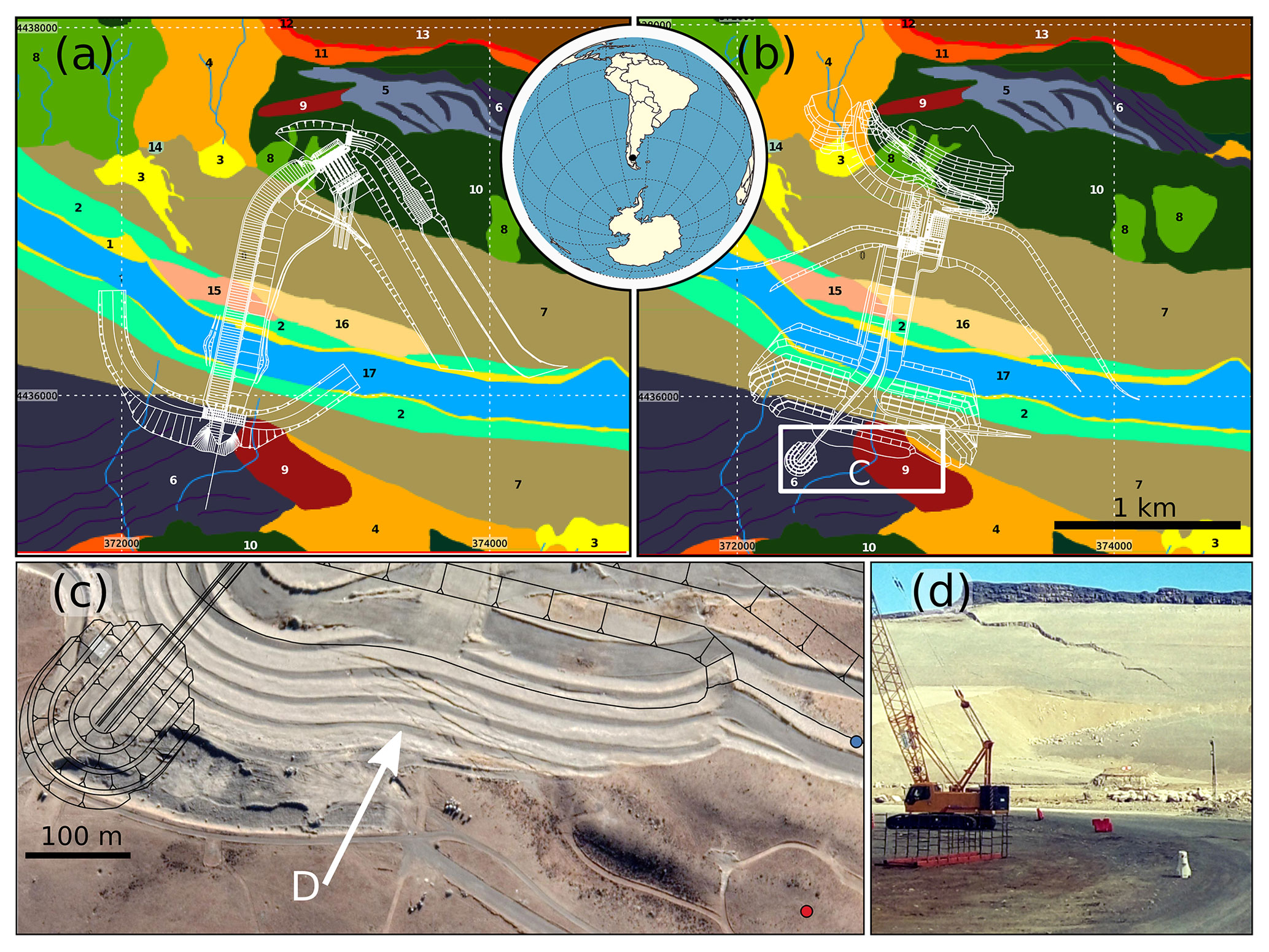
Figure 1A dot in the very center of the planisphere (between a and b) shows the project location (50.21∘ S, 70.78∘ W), and coordinates in planar system are UTM zone 19S. (a) First design of the CC-NK dam (2015). (b) Second design of the CC-NK dam after experiencing structural issues (2020). In the background, the geomorphological map with the following categories may be observed: 1 – alluvial plain; 2 – fluvial terraces; 3 – active alluvial fan; 4 – flank pediment; 5 – basal moraine; 6 – marginal moraine. 7 – glaciofluvial terrace covered by catastrophic flow deposits; 8 – rock avalanche deposits; 9 – lateral spread and rotational landslides; 10 – rotational landslides; 11 – scree slope; 12 – rockfall; 13 – lava flow; 14 – seasonal lagoon; 15 – wind blowout; 16 – parabolic dune; 17 – Santa Cruz River channel. Panel (c) shows the optical satellite image where the cracks of the south bank can be seen. In panel (d), a view from the ground of the crack on the south margin may be observed. Source: our own elaboration based on EBISA (2017) and IEASA (2020), © Google Maps, http://www.worldmapgenerator.com (last access: August 2022), and on fieldwork.
The Hydroelectric Developments of the Santa Cruz River (AHRSC in Spanish) project consists of a hydroelectric project for the simultaneous construction of two hydroelectric mega dams on that river. Once completed, its reservoirs will flood 50 % of the course of the river. This is the largest infrastructure project in Argentina in recent decades, the largest dam project under construction by Chinese companies outside China and the southernmost mega dam on the planet, with a minimum cost of USD 4.5 billion (Tamburini-Beliveau and Folguera, 2022).
Once built, the dams will have a joint installed capacity of 1310 MW with an average annual plant generation of approximately 5000 GW h−1. This will contribute to 2.5 %–5 % of the maximum peak of national electricity consumption (EBISA, 2017).
Both dams are of the concrete face rockfill dam (CFRD) type. The Cóndor Cliff–Néstor Kirchner dam (CC-NK), the larger of the two dams and the one studied in this work (Fig. 1), is 68 m high from its crest to the bottom of the channel and will store 5.3 km3 of water. The second dam, La Barrancosa–Jorge Cepernic, which is downstream from CC-NK, is 41 m high and will generate a 3.5 km3 reservoir (EBISA, 2017).
According to official documentation (IEASA, 2020), at the end of 2018 and beginning of 2019, during the foundation excavations of the main wall of the CC-NK dam, several landslides occurred in the areas of the abutments on both banks of the river, endangering the construction and, therefore, leading to the interruption of the works and the complete redesign of the dam. The new design keeps its productive characteristics but with a completely different morphology (Fig. 1a and b). Because of this situation, project deadlines and costs have substantially been affected, threatening its financial viability. Large sectors of the work already done by 2019 had to be removed to readapt the project from 2020 onwards. The structure has been substantially modified: without moving the central sector of the dam axis, its anchors have been diverted a few hundred meters upstream, also readapting the location of other key dam elements (deviation channel, machine hall, etc.) resulting in a roughly U-shaped dam very different from the original.
The geological characteristics of the CC-NK dam site hinder its construction. It is located in a canyon valley covered by loose Quaternary glaciofluvial sediments varying in thickness from 5 m to over 60 m, as well as accumulations of material from multiple mass-wasting events and paleo-slides from the same period (see geomorphological map in Fig. 1). Pliocene basaltic lava flows are also present in some elevated sectors, i.e., the tops of the plateaus on the cliffs on the margins of the river canyon (Astini et al., 2015; EBISA, 2017; IEASA, 2020, 2021).
All these materials are found over the Tertiary Santa Cruz formation, which consists of a lower Miocene homocline inclined a few degrees to the southeast. It is formed by fluviolacustrine sedimentary strata that are very heterogeneous in the vertical direction (constant and transitional alternation of sandy and pelite packages), which are weak and poorly compacted due to their low diagenesis (Astini et al., 2015; Giambastiani and Filloy, 2018; Celli and Falcioni, 2022). From the Cenozoic to the last Pleistocene glacial period, this formation has been eroded and fractured by the action of large glaciers, generating glaciotectonic faults and diaclases of various magnitudes (Strelin and Malagnino, 1996).
Additionally, the ceiling of rigid, dense and compact basaltic lava flows, which are present mainly on the northern flank of the river, favors the occurrence of mass-wasting processes due to the strong vertical contrasts between the physical characteristics of the multiple rock strata (Turazzini, 2002; Astini et al., 2015; EBISA, 2017).
Lastly, in the southern sector of the construction site, the rock (Santa Cruz formation) is too far from the surface, covered by glaciofluvial deposits, and consequently, the structure of the dam has serious difficulties for securing the foundations on (the weak) rock. On the north flank, a fault with a northwest direction at an elevation of 170–180 m is described, extending a few meters in the upper sector of the location of the axis and foundation of the dam (Capdevila et al., 2007). This fault is not represented on the project official geomorphological maps, and it is consequently also absent in the figures of this text.
From the elements presented above, it can be deduced that a difficult and complex geotechnical scenario affects the CC-NK dam and its foundations on both flanks of the wall (Beigt et al., 2016; Pánek et al., 2018).
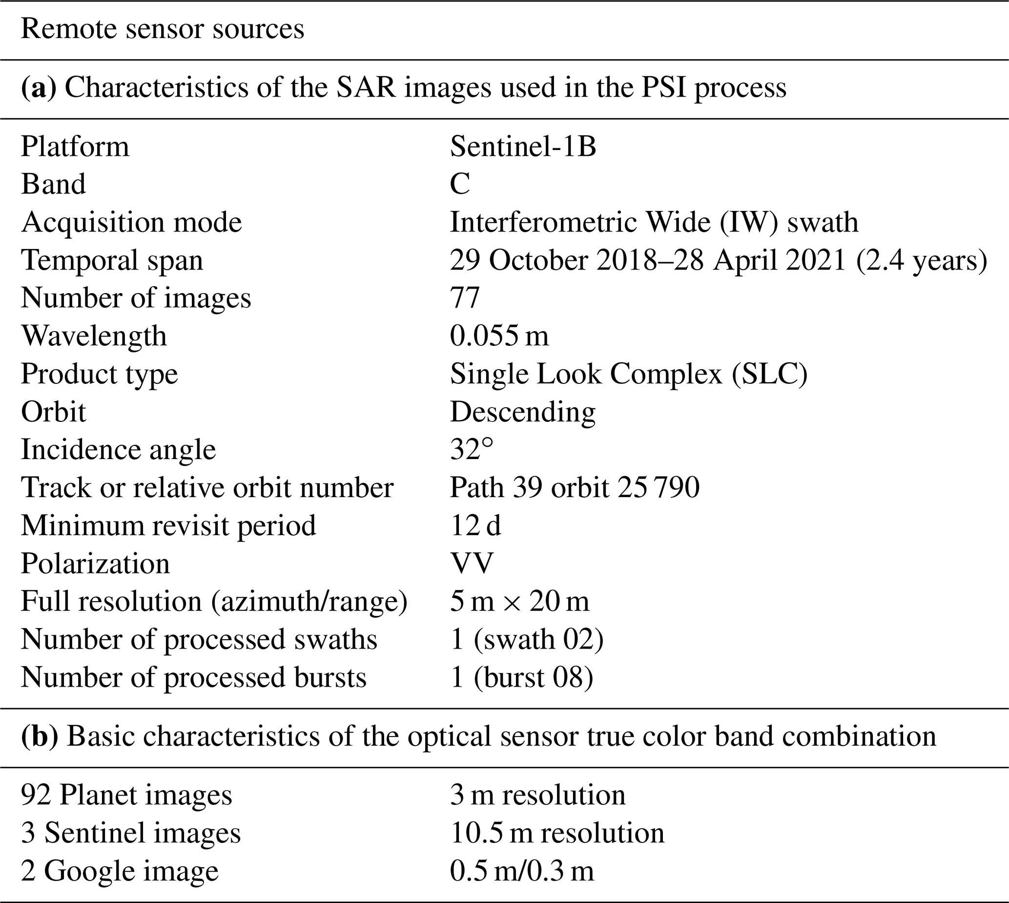
The anchorage area of the abutments of the CC-NK dam, where the slope instabilities appeared, has been analyzed with PSI during the period ranging from November 2018 to April 2021, the obtained raw data of this procedure are available as a Supplement. The particular PSI processing chain and algorithm used in this work is the PSIG approach (Devanthéry et al., 2018), developed by the Geomatics Research Unit of the Centre Tecnològic de Telecomunicacions de Catalunya, and the input source data have been acquired by the Sentinel-1 SAR satellite constellation (see Table 1a and Appendix A).
Table 1Main characteristics of the input satellite data for the research (our own elaboration).
The satellite DInSAR method exploits the phase differences measured in the radar signal between two satellite SAR images of the same area acquired at different times and from slightly different positions. The measured interferometric phase represents differences along the satellite-target travel of the radar signal. After the necessary corrections and parameterizations, the movement of the ground target between both acquisitions can be estimated.
The PSI method is an advanced DInSAR technique that exploits stacks of images acquired at different times of the same area to provide high-precision ground (or ground-fixed infrastructure) displacement measurements. This technique allows robust measurements throughout time providing displacement time series and velocity estimations for the location of each one of the measured points. Crosetto et al. (2016) provide a comprehensive review of PSI techniques. In particular, the main steps of the PSI approach used here (PSIG) consist of the selection of points with high temporal coherence (above 0.7) to obtain the unwrapped phases of these points, atmospheric filtering and time series estimation. The way how these steps have been carried out in this work is described in Krishnakumar et al. (2021). It is worth underlining that by “points” we refer to pixels of a satellite raster image representing a small portion of the surface of the Earth. The final PSI time series contains the accumulated magnitude of the deformation in correspondence with the time-ordered SAR images starting from a reference image.
Optical images have been used to monitor the evolution of the works and double-check what was revealed by the PSI results (see Table 1b). Other digital vector mapping data (geological and geomorphological maps, contour lines, and plans of the dams) have been obtained from the dam's environmental impact assessment report (EBISA, 2017), other official technical documents (IEASA, 2020, 2021; Astini et al., 2015) and an online cartography server: https://observatorio.ieasa.com.ar/geovisor.php (last access: August 2022). The information has been collected and analyzed with the QGIS software.
The main result of this work consists of a map of accumulated ground displacement of the CC-NK dam and its surroundings (Figs. 2, B1 and B2) and the displacement time series from November 2018 to April 2021. All the presented measurements are in the line of sight (LOS).
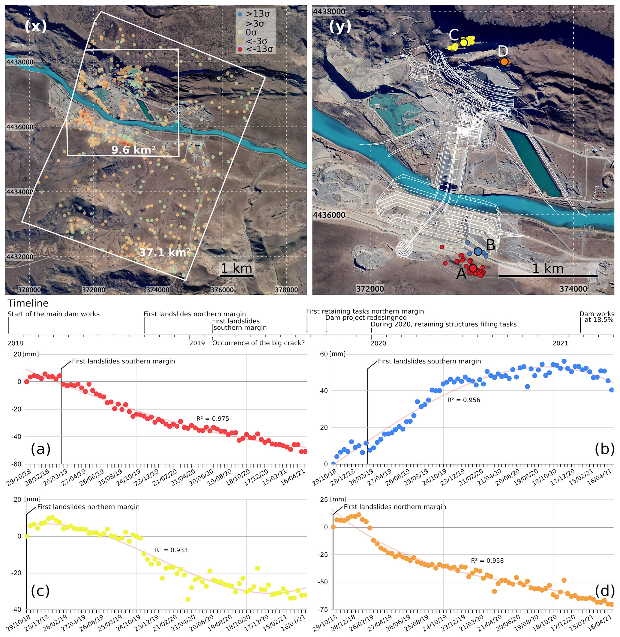
Figure 2Top left (x): area covered by the PSI processing. White polygons circumscribe the general (big polygon) and the detailed (small polygon) areas under study. The optical background image is from Google from July 2022 (© Google Maps). Coordinates are UTM zone 19S. Only reflectors showing deformation > 3σ are represented, magenta is negative and cyan is positive deviation, and scale ranges until 13σ. Top right (y): construction site. The PSs of each landslide subgroup are represented on the southern (a, b) and northern (c, d) margins. Panels (a) to (d) correspond to the deformation time series of the calculated average for each one of the landslide (a–d). The plan of the second dam design has been superimposed. A timeline showing the phases in the dam construction is found at the figure center. The period not covered by the PSI analysis is shown as a dashed line over the timeline axis.
A total of 68 477 persistent scatterers (PSs) were obtained in a region of 37.1 km2. This corresponds to a density of 1897 PSs per square kilometer, approximately one point every 527 m2 (see Figs. 2x and B2). Out of these, 1018 PSs (0.7 %) show a displacement above 3σ (σ=2.69), i.e., an accumulated deformation over 8.07 mm along the monitored period, which corresponds to a velocity displacement of 3.23 mm yr−1. The value of 3σ was taken to clearly discriminate those points with random scattered values around 0 from those showing clear deformation trends (see Fig. B1e). Consequently, to better focus the analysis, the first group of PSs displaying deformation < 3σ was discarded. Thus, only the reflectors with steep deformation trends have been analyzed (Fig. 2x).
From this initial dataset, the subregion that includes the work of the CC-NK dam was analyzed in detail (Fig. 2y; small polygon in Fig. 2x). This corresponds approximately to 9.6 km2. There, 15 678 PSs were obtained, that is 1742 PSs per square kilometer, approximately one point every 574 m2, out of which 857 (5.5 %) have magnitudes of > 3σ of the original dataset.
The 5.5 % of PSs displaying deformation > 3σ of the detailed area of interest versus the 0.7 % of the whole region reveals the evident concentration of ground displacement phenomena in the area where the dam is being built.
The results allow us to identify five area typologies showing distinct deformation behavior:
-
areas displaying negligible displacements (< 3σ already mentioned);
-
landslides on slopes, the focus of this study (see Fig. 2);
-
foreseeable deformation trends associated with the construction works, for example, terrain uplift caused by the progressive construction of a retaining slope or subsidence due to the extraction of aggregates;
-
systematic or random errors, mainly phase jumps or atmospheric errors, respectively;
-
absence of measurements, i.e., PSs, due to modification of the terrain due to the construction works – in the face of substantial changes in the surface, the possibility of attaining PSs is lost.
This paper focuses on item 2 of this list, i.e., landslides on slopes. More details on the characteristics of the other items can be found in Appendix B.
The official reports (IEASA, 2020, 2021) indicate that the two areas of the dam abutments, on both the north and south banks of the river, are affected by landslides. More precisely, PSI measurements enabled the identification of two subareas with their own deformation dynamics on each riverbank. All the PSs within each subarea were averaged, obtaining a single PSI value per subarea. The analysis of the optical images confirmed that these areas were not affected by significant changes in the ground surface during the monitored period. The largest of these areas approximately occupies an area of 2 ha and the smallest of 0.2 ha.
The results are presented in Fig. 2. On the south bank, two deformation phenomena are identified, sector A with 51 (red) PSs and sector B with 18 (blue). On the north bank the identified deformation phenomena are sector C with 33 PSs (yellow) and D with 15 (orange).
Maximum accumulated displacements between extreme values range from 40 to 80 mm. This represents 16 mm yr−1 for area C and 32 mm yr−1 in sector D. A polynomial fit line with a determination coefficient R2 (Mirmazloumi et al., 2022) has been superimposed in the chart to show the absence of noise in the measurements. It is worth underlining that the magnitudes measured do not accurately reflect the real magnitude of the movements since
-
PSI provides measurements along the LOS component, which only reflects part (a projection) of the real displacement vector;
-
PSI is opportunistic – that is, it only provides measurements on those points that provide a permanent response to the satellite;
-
the period analyzed does not cover the entire displacement period.
Sector A is located in a flat area, so it could be said that most of the movement is vertical, which, according to the orbit direction of the satellite, is in agreement with the negative values of the LOS measurement showing subsidence.
Sector B is located on the slope, so horizontal and vertical displacements are measured. The general orientation of this area is not the optimal to be observed with the descending satellite trajectory, but the considerable magnitude of the deformation facilitated obtaining results. Presumably, deformation to the west and east of the A–B locations became invisible to the radar either by the large magnitude of the ground displacements (to the west, in the crack, where data decorrelation is present; see Fig. B1i, in Appendix B) or due to the deficient orientation of the slope and the smaller magnitude of the displacements (to the east).
Observing the situation in sectors A and B (with inverse trend sign), it is possible to suggest that a rotational mass wasting is taking place, which agrees with the bibliography (Astini et al., 2015), but additional information is required to provide a more definitive conclusion.
Since sector C is mainly flat, it is possible to infer a relevant vertical component of the displacement. However, the PSI information is not enough to determine the exact direction of the deformation vector. In the chart (Fig. 2c), a step in the trend is visible in October 2019, which coincides with the start of containment works in the area as revealed by the optical sources.
Finally, as sector D is found in a steep slope, both vertical and horizontal displacements are relevant, but further measurements are required to fully understand the situation. The strong slope of the curve around February 2019 (Fig. 2d) confirms the ground instability trends described in the company reports (IEASA, 2020).
The time series of the four sectors shown in Fig. 2 show no signs of stabilization, so it is possible to affirm that the sliding processes were still active in April 2021 (date of the last observation). The construction works in general, and the deformation phenomena in particular, are clearly located in areas of Quaternary sedimentation and materials resulting from paleo-mass-wasting processes that had already been described as potentially conflictive in the preliminary project reports (see Fig. 1a and b), such as
-
on the north bank: basal moraine (8), lateral expansion and rotational slide (18), rotational slide (20);
-
and on the south bank: marginal moraine (9) and lateral expansion and rotational slide (18).
The ground dynamics described in this piece of research coincide with what may be consulted in the reports from the company contracting this study (IEASA, 2020), in which the landslides are associated with the reactivation of a paleo-slide in the southern sector and with the presence of a subhorizontal stratum whose material presented very low resistance and high plasticity in the northern sector.
The PSI technique has allowed us to confirm that, as indicated by civil organizations, the media and, finally, the official reports, slope instability processes have been activated or reactivated by the construction works, risking the integrity of the dam wall anchorages. This finding has been corroborated with optical satellite imagery and fieldwork. According to official information, the period studied should cover the beginning and the end of the slides. However, the time series of the sectors affected do not confirm the stabilization of the movements.
We have presented relevant unpublished information regarding the integrity and safety of a large-scale civil infrastructure of international importance, since the Chinese and the Argentine governments and a world-class hydrographic basin are involved. Moreover, it is relevant to note that the ongoing construction work of a dam has been monitored and tracked, while finished and operative civil infrastructure projects are the most common cases found in the literature.
With this work, we have demonstrated that it is possible to effectively and rapidly contribute to the identification of structural problems that might increase economic costs and raise safety issues of ongoing construction works by applying remote sensing techniques.
A broad, exhaustive and systematic spatiotemporal monitoring of the terrain can be attained with DInSAR techniques from the beginning of any construction work in order to identify geological risks that might pose a safety risk. It is possible to cover large areas with a high density of displacement measurements and with temporary persistence, enabling the identification of landslide processes, not requiring a priori information of the areas in which they may occur and detecting them before they generate major damage. Both infrastructure under construction and construction projects in operation might be monitored remotely, avoiding the installation of expensive instruments on the ground, which can be installed only if strictly necessary. If these techniques had been applied early in the construction project under study, the evolution of the works in the CC-NK dam could have been different. Besides, we also demonstrated how these techniques offer useful information for management authorities and local communities to independently assess the current state of projects of this kind.
In this particular case, and with a minimum investment cost, we have been able to independently and remotely monitor a serious eventuality with potential dramatic consequences for a mega dam project located in a remote region. The weaknesses in the anchorages on both sides of a dam wall of a hydropower facility system with a capacity for 8.8 km3 of water could be catastrophic if not detected in time.
Finally, and attending to the magnitude of the experienced geotechnical problems, we hope we have made a valuable contribution to the adequate and safe evolution of the AHRSC project, which is located in very challenging terrain.
We implemented the advanced differential interferometry SAR algorithm named persistent scatterer interferometry (PSI) which is particularly suitable for monitoring outcrops, urban areas and humanmade infrastructure (Devanthéry et al., 2018). The processing steps include the following: (1) data download and extraction, (2) DEM preparation, (3) processing chain configuration, (4) estimation of velocity of deformation (processing), (5) phase unwrapping and time series estimation, and (6) geocoding.
A temporal baseline limit of 100 d has been applied to the interferometric pairs. Due to the small orbital tunnel configuration of the Sentinel-1 mission (i. e. short spatial baseline), the most important decorrelation factor comes from the surface changes throughout time. No perpendicular baseline limit has been applied.
A total of 77 high-resolution SAR scenes covered the period from 29 October 2018 to 28 April 2021 (2.4 years), with a 12 d revisit time. The Single Look Complex (SLC) product and Interferometric Wide (IW) acquisition mode were selected and downloaded from the online ESA Copernicus Open Access Hub. The precise orbit files were downloaded from the Copernicus Sentinels POD Data Hub.
For each SAR image, the co-polar vertical–vertical (VV) channel was extracted from the original data in double polarization (VV + VH – vertical–horizontal) and the corresponding swath of the area of interest (IW2). The 30 m spatial resolution digital elevation model of the Shuttle Radar Topography Mission (SRTM) was used to calculate the topographic component that was later extracted. The DEM tiles were downloaded from the United States Geological Survey (USGS) EarthExplorer catalog.
A transformation of the DEM to the SAR geometry of the super-master image was carried out. Interferometric pairs and corregistration were created between them. Interferometric phase quality indicators were created, such as the amplitude and the average dispersion. We generated 580 high-resolution differential interferograms. The deformation velocity and the residual topographic error were estimated. Then, the selection of the suitable points where the final solution would be obtained was carried out. Other parameters defined for the PSs inclusion for the final result dataset were (1) a maximum threshold of the average dispersion of the amplitude of 0.50 and (2) a temporal coherence maximum value of 0.65.
Finally, the interferometric phase unwrapping was performed, obtaining the absolute deformation values for each PS. The final coordinates of the PSs are offered in a global geographic coordinate system, based on a reference ellipsoid. Thereby, a georeferenced point cloud was obtained with information on the absolute displacements for each acquisition date and the deformation velocity, which allowed us to display, compare and analyze the deformation time series in a geographic information system (GIS).
Figures B1 and B2 show examples of PSs with high σ values that have not been included in this work and correspond to items enumerated in Sect. 6, and in the following they are briefly described. The letter notation is the same for both figures.
-
(e) Frequency distribution graph of the accumulated displacement of the PS reflectors in the study area and the 3σ threshold.
-
(f) Time series of a stable PS with dispersed measurements due to random errors: elevated σ between 2 and 3, R2=0.082.
-
(g) Phase unwrapping error (PUE). 40 reflectors average. Red dots in the chart in Fig. B1 represent the series after applying a manual PUE correction jump of 28 mm (Mirmazloumi et al., 2022).
-
(h) Deformation trend (Fig. B1h1) caused by construction works (Fig. B1h2). 72 reflectors average.
-
(i) 11 phase unwrapping errors for a single reflector located in the root of the big crack in the southern margin (west of studied sectors A and B). This is an exceptional and isolated sample which preserved the coherence along the time series despite the high deformation rate. Chart in Fig. B1i2 indicates the deformation trend without PUE correction. Figure B1i3 corresponds to the same chart after applying a manual PUE correction. A visual detail of the crack is shown in Fig. B1i3 and the location of that reflector in Fig. B2 as a grey diamond. Official documentation describes the occurrence of the landslide on 14 February 2019. This is clearly visible in the charts (first vertical dashed red line). At the same time, it is clear that the trend was present before (at lower rates) and after this date. Vertical dashed red lines indicate the enforcement of a PUE correction, 11 times in this case. Official reports (IEASA, 2021) describe ground displacements of up to 15 mm d−1 (5.5 m yr−1) in the main sector of this big crack, where we could not obtain PSI. Observing this chart, we cannot confirm the end of the deformation trend in April 2021.
Figure B3 presents three stages of the project evolution through optical sensors where main project changes can be seen.
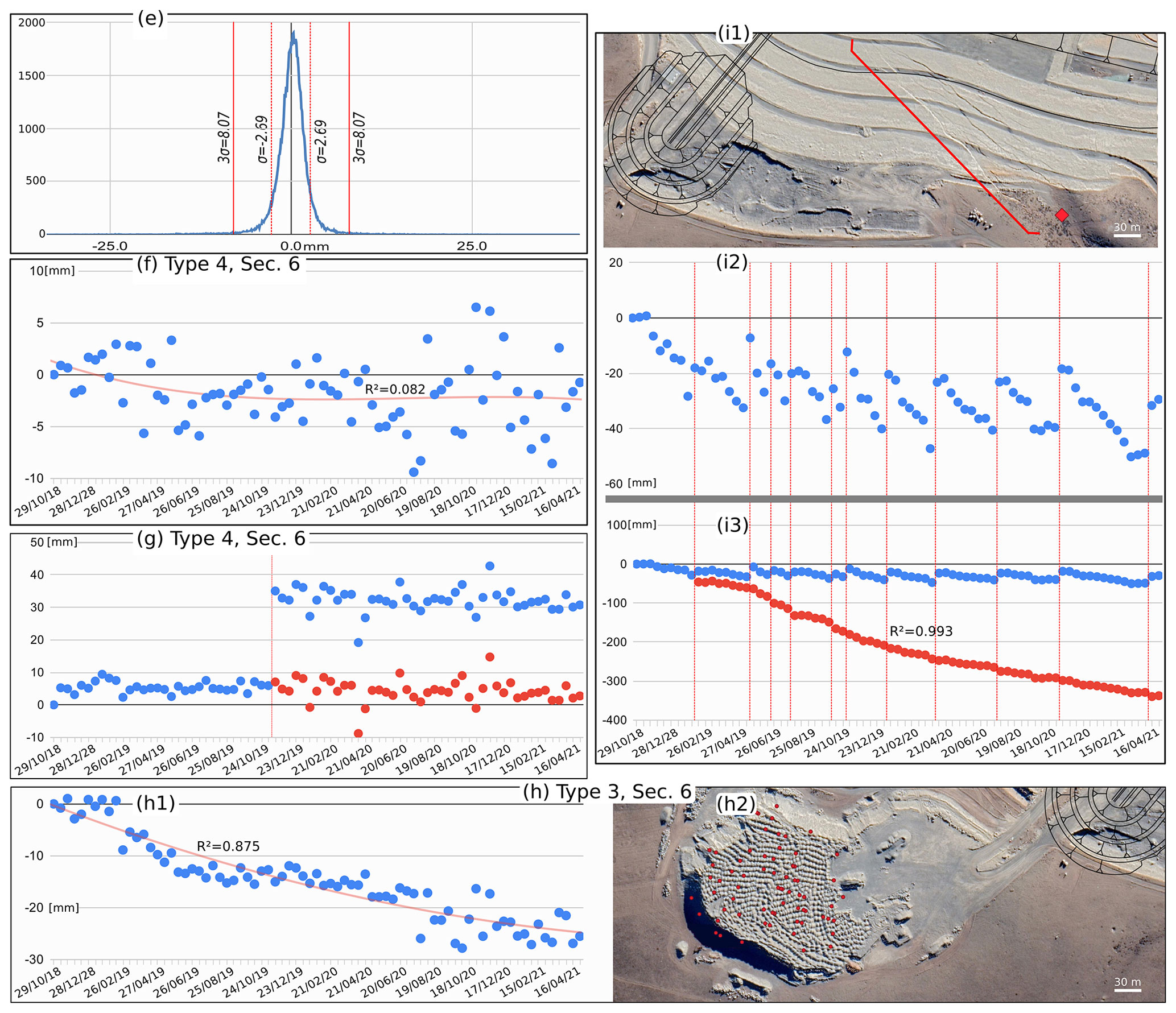
Figure B1(e) Frequency distribution of the PSs of the whole dataset. (f–h) Examples of PSs with high values which, as presented in Sect. 6 and following the same number notation, have not been studied in this work. Letter notation is also coincident with the one in Fig. B2. Optical satellite images from © Google Maps.
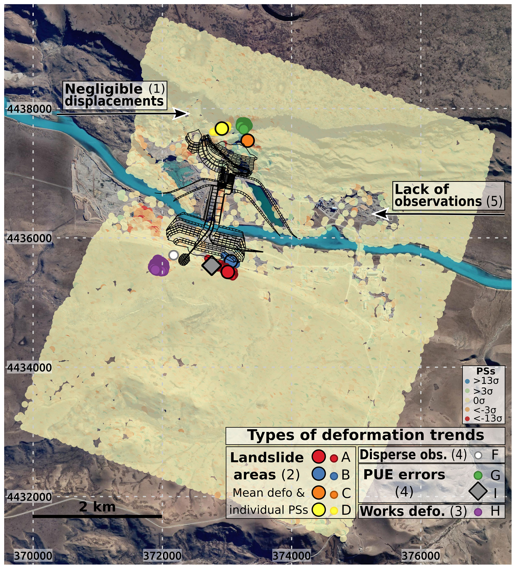
Figure B2Map of the full PSI results and examples of the identified deformation trends. Following previous notation A to D are landslides studied in this work as presented in Fig. 2; F to I are the trends presented in Fig. B1. Numbers correspond to the deformation typologies enumerated in Sect. 6. The trends can be identified in the map by the symbol represented in the legend. Arrows, numbers 1 and 5 as in Sect. 6, are examples of observations with negligible displacements (< 3σ) and absence of observations due to the surface changes produced by the construction work, respectively. Our own elaboration. Background satellite image © Google Maps.
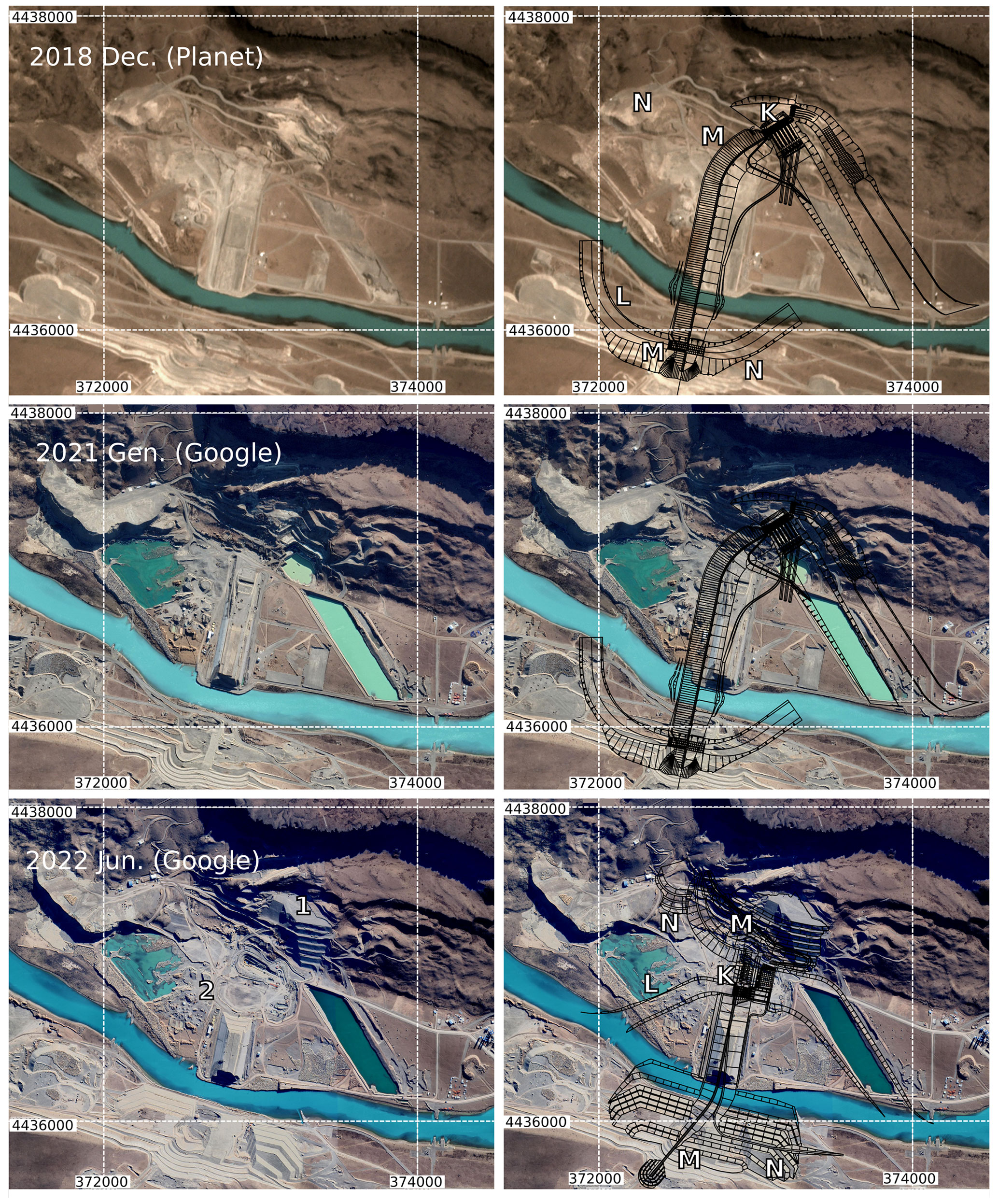
Figure B3Three moments of the dam construction. In the left column are optical images, and in the right, the dam plans have been superimposed (the third row corresponds to the new project). Letters identify main structural changes: K – machine hall; L – deviation channel; M – change in the dam wall direction; N – structural retaining walls. Numbers identify main correction works to the original project (modification of structures already built): 1 – the space prepared for the main hall has been filled in again (over 1×10⁶ m3); 2 – an important part of the dam wall (which was originally planned to have 12.1×10⁶ m3) has been retired, and a big 10 m wide and 36 m deep exploratory well has been built there to study the rock substratum. To dig the well, a volume of around 70 000 m3 had to be previously removed at the ground level in the area which had already been filled with basement materials of the dam wall. Our own elaboration. Background images from Planet™ and © Google Maps.
The data from the Sentinel satellite platforms can be freely accessed from https://scihub.copernicus.eu/dhus/#/home (ESA, 2023a; https://sentinel.esa.int/web/sentinel/technical-guides/sentinel-1-sar/products-algorithms/level-1/single-look-complex/interferometric-wide-swath, ESA, 2023b). The raw dataset used in this work is attached as a Supplement.
The supplement related to this article is available online at: https://doi.org/10.5194/nhess-23-1987-2023-supplement.
GTB coordinated the team, wrote the text, designed the figures and performed the general research over the study case: geological setting, engineering and environmental impact assessment, technical report analysis, available data, etc. SB processed the PSI data and developed the methods section. OM carried out a general supervision of the research work.
The contact author has declared that none of the authors has any competing interests.
Publisher’s note: Copernicus Publications remains neutral with regard to jurisdictional claims in published maps and institutional affiliations.
We thank to the Spanish grant SARAI for funding this project. We also thank LaIC (Laboratorio de Inglés Científico – UNPA) and María Cuevas-González for their linguistic support and corrections of the manuscript.
This work is part of the Spanish grant SARAI, PID2020-116540RB-C21, funded by MCIN/AEI/10.13039/501100011033.
This paper was edited by Daniele Giordan and reviewed by two anonymous referees.
Astini, R., del Papa, C., Nóbile, J., Martini, M., Malagnino, E., and Piovano, E.: Informe Investigación geológica, sedimentológica, estratigráfica y geomorfológica Valle del Río Santa Cruz – Provincia Santa Cruz – Argentina, Tech. rep., CICTERRA, CONICET, Universidad Nacional de Córdoba, https://www.conicet.gov.ar/new_scp/detalle.php?keywords=&id=20006&convenios=yes&detalles=yes&conv_id=5618398 (last access: May 2023), 2015. a, b, c, d, e, f
Beigt, D., Villarosa, G., Gómez, E. A., and Manzoni, C.: Subaqueous landslides at the distal basin of Lago Nahuel Huapi (Argentina): Towards a tsunami hazard evaluation in Northern Patagonian lakes, Geomorphology, 268, 197–206, https://doi.org/10.1016/j.geomorph.2016.06.004, 2016. a
Capdevila, E. O., Massabie, A., Cuesta, R., Barletta, R., and Pérez, N.: Estudios geológicos y geotécnicos en Cóndor Cliff y La Barrancosa y alternativas de represas. Santa Cruz, Argentina, Tech. rep., IATASA, Buenos Aires, 2007. a
Celli, A. E. and Falcioni, F. E.: Caracterización geomecánica del macizo rocoso de la Formación Santa Cruz aflorante en la zona de Condor Cliff, río Santa Cruz, Patagonia Argentina, Revista de la Asociación Geológica Argentina, 79, 106–124, 2022. a
Crosetto, M., Monserrat, O., Cuevas-González, M., Devanthéry, N., and Crippa, B.: Persistent Scatterer Interferometry: A review, ISPRS J. Photogramm., 115, 78–89, https://doi.org/10.1016/j.isprsjprs.2015.10.011, 2016. a, b, c
Devanthéry, N., Crosetto, M., Monserrat, O., Cuevas-González, M., and Crippa, B.: Deformation Monitoring Using Sentinel-1 SAR Data, in: The 2nd International Electronic Conference on Remote Sensing, MDPI, online, 22 March–5 April 2017, https://doi.org/10.3390/ecrs-2-05157, 2018. a, b, c
EBISA: Aprovechamientos Hidroeléctricos del río Santa Cruz. Estudio de Impacto Ambiental, Tech. rep., EBISA, https://observatorio.ieasa.com.ar/ (last access: August 2021), 2017. a, b, c, d, e, f
ESA: Copernicus Open Access Hub, European Space Agency, https://scihub.copernicus.eu/dhus/#/home, last access: May 2023a. a
ESA: Sentinel Online Technical Guides: Level-1 Interferometric Wide Swath SLC Products, European Space Agency [data set], https://sentinel.esa.int/web/sentinel/technical-guides/sentinel-1-sar/products-algorithms/level-1/single-look-complex/interferometric-wide-swath, last access: May 2023b. a, b
Giambastiani, M. and Filloy, J. E.: Geología y geotecnia de la presa Cóndor Cliff, río Santa Cruz, provincia de Santa Cruz, Argentina, in: IX Congreso Argentino de Presas y Aprovechamientos Hidroeléctricos, Mendoza, Argentina, 16–19 May 2018, Comité Argentino de Presas, https://www.researchgate.net/publication/327273184_GEOLOGIA_Y_GEOTECNIA_DE_LA_PRESA_CONDOR_CLIFF_RIO_SANTA_CRUZ_PROVINCIA_DE_SANTA_CRUZ_ARGENTINA (last access: May 2023), 2018. a
IEASA: Aprovechamientos hidroeléctricos del río Santa Cruz Cóndor Cliff y La Barrancosa. Ajuste del Proyecto Ejecutivo de Cóndor Cliff por los deslizamientos, Tech. rep., IEASA, 2020. a, b, c, d, e, f, g, h
IEASA: Planta hidroeléctrica Condor Cliff. Misión del Panel de Abril de 2021. Informe final, Tech. Rep. N. Ref.: 6755.0-R-08, IEASA, 2021. a, b, c, d
Krishnakumar, V., Qiu, Z., Monserrat, O., Barra, A., López-Vinielles, J., Reyes-Carmona, C., Gao, Q., Cuevas-González, M., Palamà, R., Crippa, B., and Gili, J. A.: Sentinel-1 A-DInSAR Approaches to Map and Monitor Ground Displacements, Remote Sens., 13, 1120, https://doi.org/10.3390/rs13061120, 2021. a
Lumbroso, D., Davison, M., Body, R., and Petkovšek, G.: Modelling the Brumadinho tailings dam failure, the subsequent loss of life and how it could have been reduced, Nat. Hazards Earth Syst. Sci., 21, 21–37, https://doi.org/10.5194/nhess-21-21-2021, 2021. a
Masiokas, M. H., Cara, L., Villalba, R., Pitte, P., Luckman, B. H., Toum, E., Christie, D. A., Quesne, C. L., and Mauget, S.: Streamflow variations across the Andes (18∘–55∘ S) during the instrumental era, Sci. Rep., 9, 17879, https://doi.org/10.1038/s41598-019-53981-x, 2019. a
Mirmazloumi, S. M., Wassie, Y., Navarro, J. A., Palamà, R., Krishnakumar, V., Barra, A., Cuevas-González, M., Crosetto, M., and Monserrat, O.: Classification of ground deformation using sentinel-1 persistent scatterer interferometry time series, GIScience Remote Sensing, 59, 374–392, https://doi.org/10.1080/15481603.2022.2030535, 2022. a, b
Moya, L., Garcia, F., Gonzales, C., Diaz, M., Zavala, C., Estrada, M., Yamazaki, F., Koshimura, S., Mas, E., and Adriano, B.: Brief communication: Radar images for monitoring informal urban settlements in vulnerable zones in Lima, Peru, Nat. Hazards Earth Syst. Sci., 22, 65–70, https://doi.org/10.5194/nhess-22-65-2022, 2022. a
Pánek, T., Korup, O., Lenart, J., Hradecký, J., and Břežný, M.: Giant landslides in the foreland of the Patagonian Ice Sheet, Quaternary Sci. Rev., 194, 39–54, https://doi.org/10.1016/j.quascirev.2018.06.028, 2018. a
Shugar, D. H., Jacquemart, M., Shean, D., Bhushan, S., Upadhyay, K., Sattar, A., Schwanghart, W., McBride, S., de Vries, M. V. W., Mergili, M., Emmer, A., Deschamps-Berger, C., McDonnell, M., Bhambri, R., Allen, S., Berthier, E., Carrivick, J. L., Clague, J. J., Dokukin, M., Dunning, S. A., Frey, H., Gascoin, S., Haritashya, U. K., Huggel, C., Kääb, A., Kargel, J. S., Kavanaugh, J. L., Lacroix, P., Petley, D., Rupper, S., Azam, M. F., Cook, S. J., Dimri, A. P., Eriksson, M., Farinotti, D., Fiddes, J., Gnyawali, K. R., Harrison, S., Jha, M., Koppes, M., Kumar, A., Leinss, S., Majeed, U., Mal, S., Muhuri, A., Noetzli, J., Paul, F., Rashid, I., Sain, K., Steiner, J., Ugalde, F., Watson, C. S., and Westoby, M. J.: A massive rock and ice avalanche caused the 2021 disaster at Chamoli, Indian Himalaya, Science, 373, 300–306, https://doi.org/10.1126/science.abh4455, 2021. a, b
Strelin, J. A. and Malagnino, E. C.: Glaciaciones pleistocenas del Lago Argentino y alto valle del río Santa Cruz, in: XIII Congreso Geológico Argentino y III Congreso de Exploración de Hidrocarburos, Buenos Aires, Argentina, 13–18 October 1996, Actas IV, vol. 4, 311–325, https://www.researchgate.net/publication/281466270_Glaciaciones_Pleistocenas_de_Lago_Argentino_y_Alto_Valle_del_Rio_Santa_Cruz (last access: May 2023), 1996. a
Tamburini-Beliveau, G. and Folguera, G. A.: Deconstruyendo a las megarepresas en el río Santa Cruz de la Patagonia argentina: cara y cruz del discurso oficial, in: Andes meridionales – Patagonia. La formación de un espacio global para la expansión del capital, CONICET, chap. 11, CONICET, Buenos Aires, ISBN 978-987-814-149-7, 2022. a
Turazzini, G. E.: Aprovechamientos hidráulicos, in: Relatorio del XV Congreso Geológico Argentino, XV Congreso Geológico Argentino, 23–26 April 2002, El Calafate, Santa Cruz, Asociación Geológica Argentina, Centro Nacional Patagónico – CONICET, vol. 2, 799–813, 2002. a
- Abstract
- Introduction
- Dam project location
- Hydroelectric Developments of the Santa Cruz River project
- Geological framework and problems of the Cóndor Cliff–Néstor Kirchner (CC-NK) mega dam
- Methods and data
- Results
- Discussion
- Conclusions
- Appendix A: Methods
- Appendix B: Supplemental figures
- Data availability
- Author contributions
- Competing interests
- Disclaimer
- Acknowledgements
- Financial support
- Review statement
- References
- Supplement